173
Task Procedures Illustrations
LEGACY
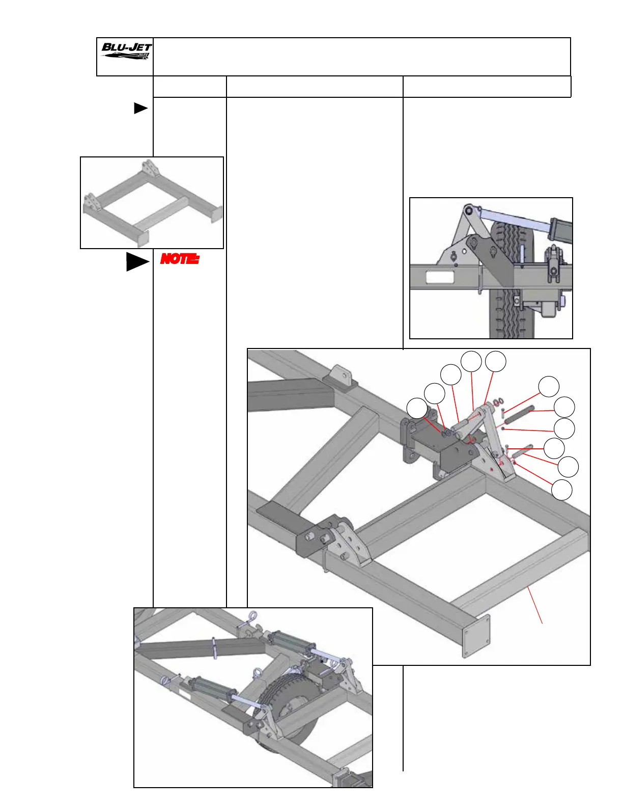
Standard Secondary Wing Linkage
Mounting
standard
secondary
wing linkage
NOTE:
Left-hand
and
right-hand
as viewed
from the
rear
1. Insert (a) (AM6197) wing
linkage 12-1/4” w/1-1/4” hole
into standard secondary wing
hinge weldment. Insert (b)
(BM3817) 1” x 6-7/8” with
13/32” hole headed with
groove through hinge weld-
ment into linkage.
Secure pin with (c) (BP3115)
3/8” x 2” hex cap screw and
(d) (CP2660) 3/8” hex lock
nut. .
2. Install (e) (AM6189) secondary
wing linkage with (f) (BM3816)
1-1/4” x 9-13/16” pin. Secure
with (i) (BP3096) 3/8” x 2-1/2”
hex cap screw and (j) (CP2660)
3/8” hex lock nut.
g
f
h
i
j
k
e
3. When cylinder or cylinders
are extended attach linkages
with (k) (BM3548) 1-1/4” x
4-3/4” double grooved pin.
Secure with (g) (BP3249)
1-7/8” OD x 1-1/4” ID
machinery bushings and
(h) (AP2711) 1-1/4” snap
rings.
c
d
b
Primary Wing
Standard
Secondary
Wing
Legacy 47’
Legacy 42’
Legacy 52’
a