157
Task Procedures Illustrations
LEGACY
a
b
d
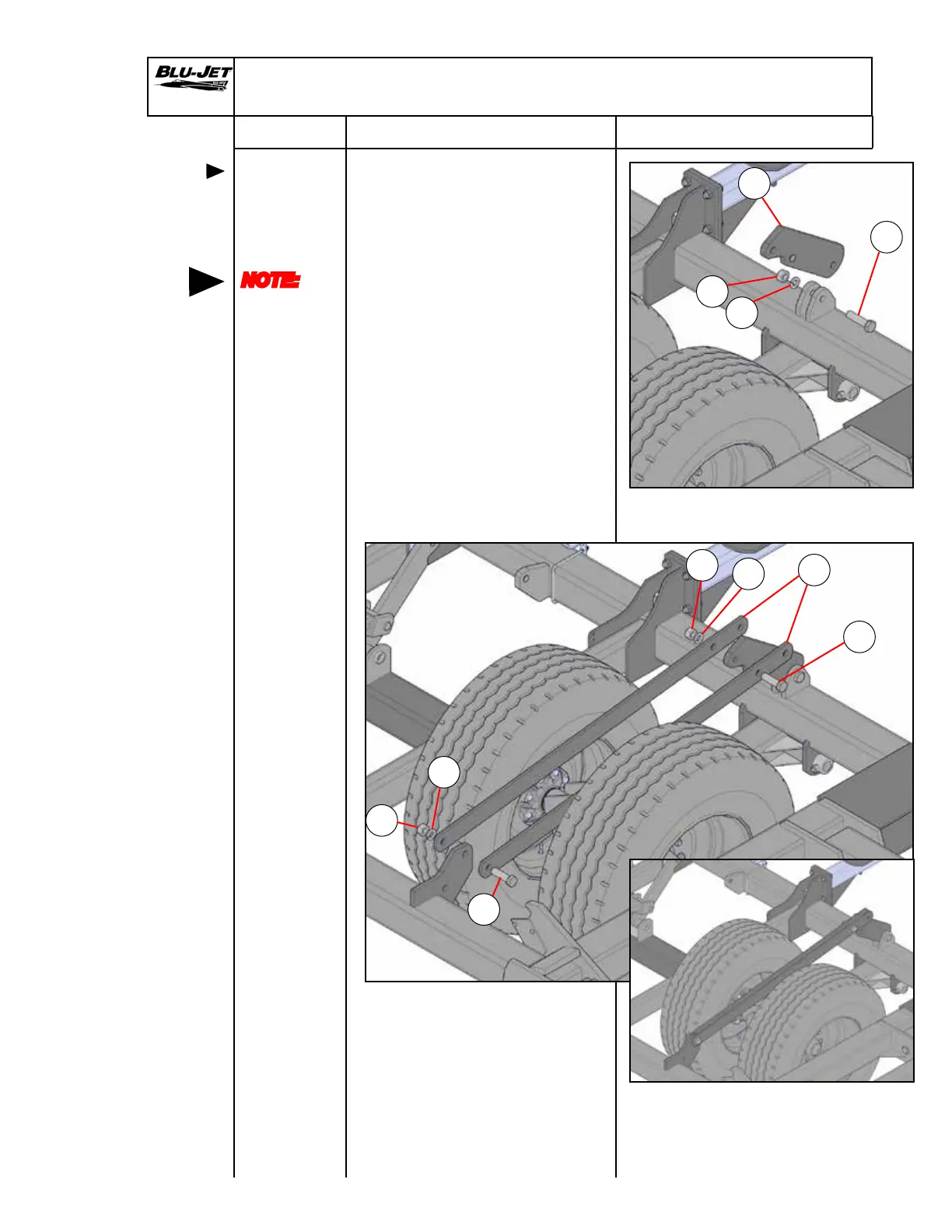
Mounting
wheel lift
linkage
NOTE:
Left-hand
and
right-hand
as viewed
from the
rear
Center Section Wheel Lift Linkage Assembly
1. Attach (a) (AM6182) bolt-on
cylinder lug with (b) (BP3291)
1” x 4”, grade 5 hex cap
screw, (c) (BP3020) 1” lock
washer and (d) (BP3019) 1”
hex nut to rear main frame
weldment.
2. Install (e) (AM6179) cylinder
lug linkages to tractor side
weldment with (f) (BP3200)
1” x 3-1/2” grade 5 hex cap
screw, (c) (BP3020) 1” lock
washer and (d) (BP3019) 1”
hex nut.
3. Secure lug linkage to bolt-on
cylinder lug with (f) (BP3200)
1” x 3-1/2” grade 5 hex cap
screw, (c) (BP3020) 1” lock
washer and (d) (BP3019) 1”
hex nut.
Rear
f
d
c
c
e
f
d
c
 Loading...