45 MT55 Operation & Maintenance Manual
ATTACHMENTS (CONT’D)
Installing And Removing The Attachment (Common Industry Interface) (Cont’d)
Installing (Cont’d)
Figure 48
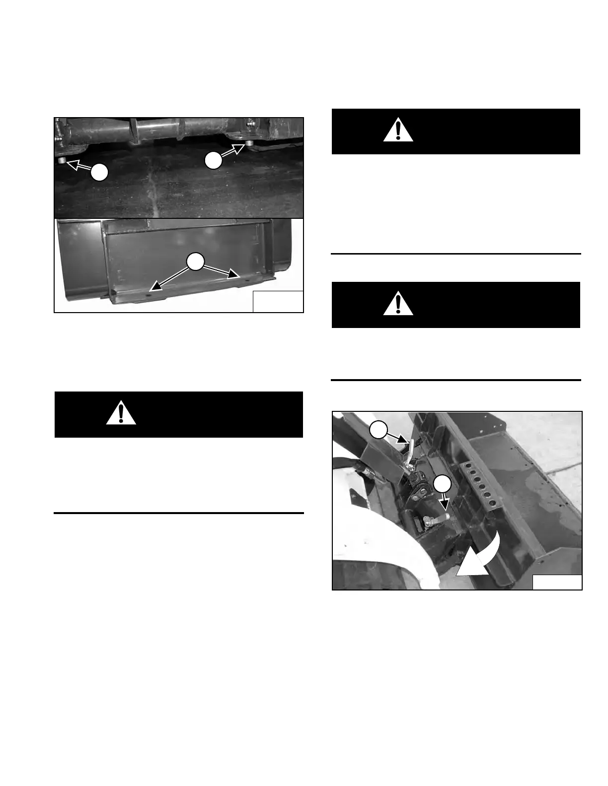
The pins (Item 1) must extend through the holes in the
mounting frame of the bucket (or other attachment) (Item
2) [Figure 48], securely fastening the attachment to the
interface.
The Common Industry Interface locking pins must
extend through the holes in attachment frame.
Levers must be fully down and locked. Failure to
secure the locking pins can allow attachment to
come off and cause serious injury or death.
W-2996-1015
Removing
Lower the lift arms, put the attachment flat on the ground
and lower or close the hydraulic equipment.
Stop the engine and engage the parking brake.
If the attachment is hydraulically controlled (combination
bucket, tiller, etc.) stop the engine and relieve hydraulic
pressure at the quick couplers. (See Relieve Hydraulic
Pressure (Mini Track Loader And Attachment) on Page
31.) Disconnect auxiliary hydraulic hoses.
Before you leave the operator’s position at the rear of
the loader:
• Lower lift arms and put attachment flat on
ground.
• Disengage auxiliary hydraulic system.
• Engage parking brake.
• Stop engine. Remove key.
W-2416-1015
Locking pin levers have spring tension. Hold lever
tightly and release slowly. Failure to obey warning
can cause injury.
W-2997-1015
Figure 49
Pull the CII locking pin levers (Item 1) [Figure 49] all the
way up.
Perform the PRE-STARTING PROCEDURE. (See PRE-
STARTING PROCEDURE on Page 37.) Start the engine.
Release the parking brake.
Be sure the lift arms are all the way down. Tilt the Bob-
Tach forward. Move backward, away from the bucket or
attachment.
Dealer Copy -- Not for Resale