787 Flight Crew Operations Manual
DO NOT USE FOR FLIGHT
Flight Instruments, Displays -
Navigation Displays
Copyright © The Boeing Company. See title page for details.
D615Z003-TBC 10.40.21
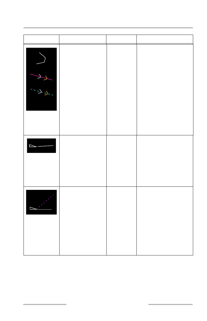
Symbol Name ND Mode Remarks
Decision gates (W, A) MAP, MAP
CTR
Indicates suggested points
where airplane should be
path and speed stable on
approach. Gates are placed
on the 3º Reference Line or
FMC Approach Glidepath
Angle Line:
• at 1000 feet above
field elevation (W)
• at 500 feet above
field elevation (A)
Decision gates that are
below the missed approach
waypoint altitude are not
displayed.
Flight path vector (W) MAP, MAP
CTR
Fixed length line indicates
current flight path angle
and rotates about the point
of the triangle.
Angle of the line is
dependent on the vertical
speed and groundspeed of
the airplane.
MCP selected vertical
speed vector or flight
path angle (M)
MAP, MAP
CTR
Dashed line indicates the
selected vertical speed as a
target angle when the MCP
V/S mode is selected.
Indicates selected flight
path angle when MCP FPA
mode is selected.
Extends to the edge of the
background display and
rotates about the point of
the triangle.
February 15, 2010