EN
25
Installation
www.bora.com
6.6 Installing the appliance in
exhaust air mode (PUXA, PURA)
i
National and regional laws and regulations must be
observed with regard to the exhaust duct design.
i
A sufficient air supply must be ensured.
i
The exhaust air must be directed to the outside by
appropriate exhaust air ducts.
i
The minimum cross-section of the air ducts must be
176 cm
2
, which equates to a round pipe with a diameter
of 150 mm or the BORA Ecotube duct system.
i
As a general rule, with the built-in fan, a length of duct
of up to 6 metres with six 90° bends, 8 metres with four
90° bends or 10 metres with two 90° bends can be
installed.
i
Not compatible with BORA Universal fans.
i
Planning instructions for the installation of the exhaust
air ducts are provided in the BORA ventilation handbook.
6.6.1 Preparing kitchen units for the exhaust
air model
XO
Cross bars on the kitchen unit in the area of the worktop cut-
out may need to be removed.
XO
In the case of thin worktops, there must be a sufficiently rigid
support plate on the unit.
XO
The back wall of the floor unit must be adapted for the
exhaust air duct.
XO
A minimum clearance of 120 mm between the back wall of
the unit and an adjacent kitchen unit or room wall must be
observed for the air duct.
XO
No false floor is necessary below the cooktop. If cable
protection (false floor) is planned, the following must be taken
into account:
XO
It must be fitted in such a way that it can be removed
from below for maintenance work.
XO
To ensure sufficient cooktop ventilation, a minimum
distance of 15 mm to the bottom edge of the cooktop is
to be observed.
XO
The drawers and/or shelves in the floor unit must be
removable.
XO
For correct installation, the drawers of the floor unit must be
shortened depending on the installation situation.
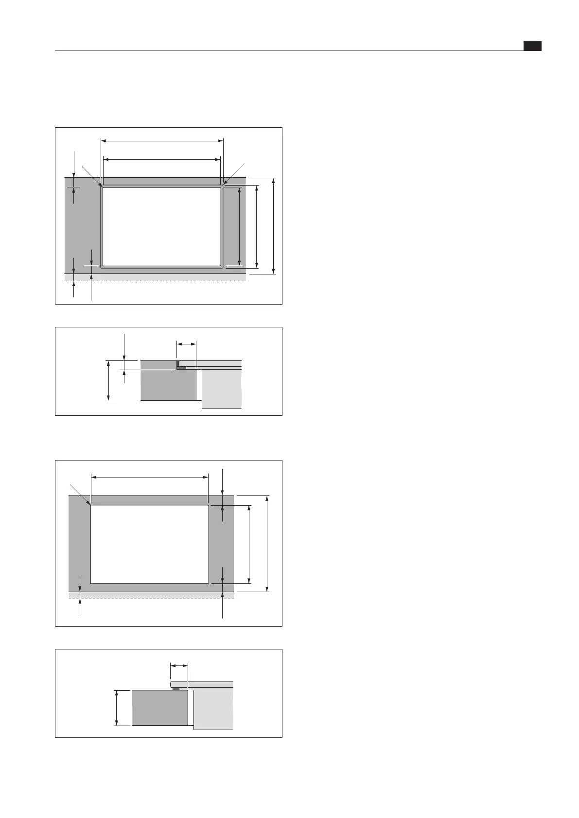
6.5.2 Pure cut-out dimensions (PURA, PURU)
Pure flush installation (PURA, PURU)
x
764 ±2
740 ±2
519 ±2
≤ R5
≤ R5
≥ 50
(≥ 50)
495 ±2
≥ 600
Fig. 6.11 Cut-out dimensions for ush installation
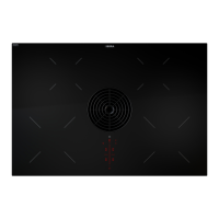
7 +0,5
12
10 - 40
Fig. 6.12 Rebate dimensions for ush installation
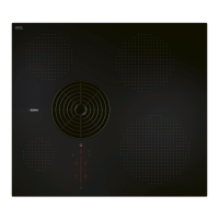
Pure surface mounting (PURA, PURU)
x
740 ±2
≤ R5
≥ 50
(≥ 50)
495 ±2
≥ 600
Fig. 6.13 Cut-out dimensions for surface mounting
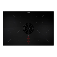
10
10 - 40
Fig. 6.14 Overlay dimensions for surface mounting