EN
30
Installation
www.bora.com
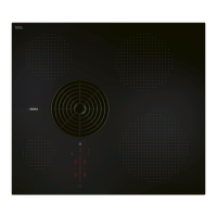
Adjusting the back wall of the unit
XX
Adapt the back wall according to the required installation
dimensions.
XX
If necessary, move the back wall.
XX
If necessary, extend the height of the back wall so that the
unit is closed to the front.
132
125
137
445
132
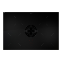
Fig. 6.28 Return ow aperture cut-out
(68,5)
(222,5)
137
PUXU/PURU
Schablone für Rückwandausschnitt
Template for cut-out on rear wall
R12,5
PURUBP-001
132
125
445
132
10
20
30
40
0
10
20
30
40
0
10
20
30
40
0
10
20
30
40
0
Fig. 6.29 Template for back wall cut-out
XX
Position the template on the back wall of the unit with the help
of the markings and instructions.
i
Centre of cut-out (horizontal): 125 mm from the top
edge of the cooktop. Centre of cut-out (vertical): offset
132 mm from the centre of the cooktop.
XX
Draw the bore hole accordingly with the aid of the drilling
template provided.
XX
Saw out the return flow aperture.
6.7.3 Preparing kitchen units for installation
variant A (floor unit with continuous
back wall)
XO
Cross bars on the kitchen unit in the area of the worktop cut-
out may need to be removed.
XO
In the case of thin worktops, there must be a sufficiently rigid
support plate on the unit.
XO
The floor unit must have a continuous back wall so that the
recirculated air is not directed into the front furniture body
compartment.
XO
There must be a cut-out in the back wall.
XO
A minimum clearance of 25 mm between the back wall of
the unit and an adjacent kitchen unit or room wall must be
observed for the return flow of the recirculated air.
XO
No false floor is necessary below the cooktop. If cable
protection (false floor) is planned, the following must be taken
into account:
XO
it must be fitted in such a way that it can be removed for
maintenance work.
XO
To ensure sufficient cooktop ventilation, a minimum
distance of 15 mm to the bottom edge of the cooktop is
to be observed.
XO
The drawers and/or shelves in the floor unit must be
removable.
XO
For correct installation, the drawers of the floor unit must be
shortened depending on the installation situation.
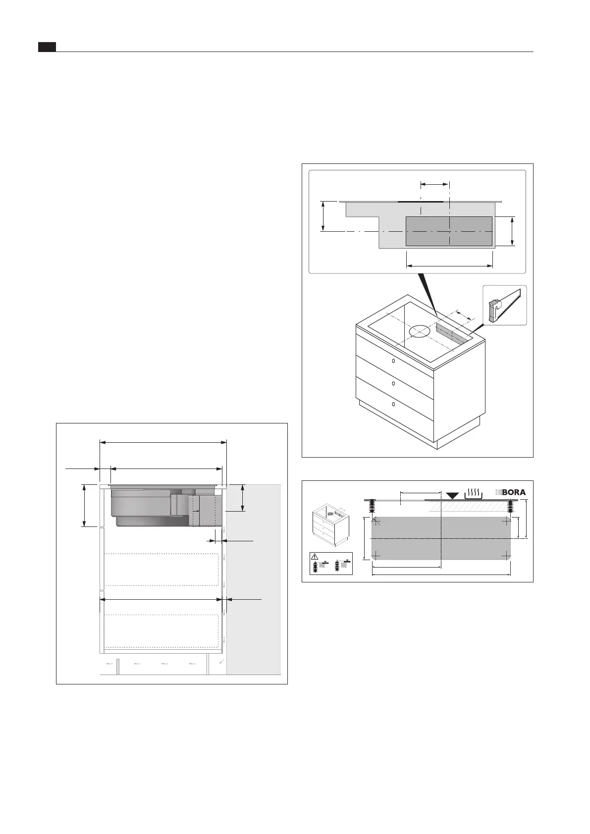
Installation dimensions
min.
600
min.
50
199
495
-
575
0
-
80
min.
25
575
(min.
545)
125
min.
675
min.
50
199
600
-
680
105
-
185
min.
25
min.
650
125
Einbauschnitt
PUXA
Abluft
(Insel):
Einbauschnitt
PUXU
(Zeile
600):
Einbauschnitt
PUXA
Abluft
(Zeile
600):
BORA X
Pure
Einbauschnitt
PUXU
mit
zusätzlichem Teleskopauszug
PULBTA (Insel):
min.
600
min.
50
199
120
585
(min.
474)
max.
480
60
min.
455
min.
329
min.
100
97
310
700
(min.
600)
min.
50
199
120
685
max.
580
min.
455
50
min.
279
min.
100
97
60
310
Fig. 6.27 Installation dimensions in the case of recirculated air,
installation variant A