EN
35
Installation
www.bora.com
Connection Fuse
protection
Minimum
cross-section
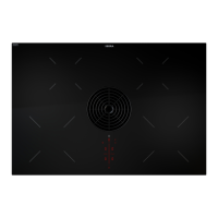
Three-phase connection 3 x 16 A 2.5 mm
2
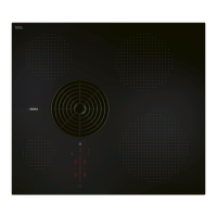
Two-phase connection 2 x 16 A 2.5 mm
2
One-phase connection 1 x 32 A 4 mm
2
Tab. 6.2 Fuse protection and minimum cross-section
Fig. 6.47 Connection diagram – three-phase connection
Fig. 6.48 Connection diagram – two-phase connection
Fig. 6.49 Connection diagram – one-phase connection
3
2
1
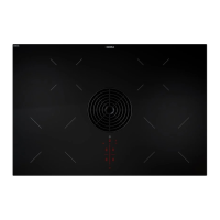
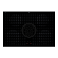
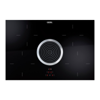
Fig. 6.50 Electrical connections of the cooktop
[1] Power supply
[2] Power supply cover
[3] Mounting eyes
6.8 Establishing the power
connection
XX
Observe all safety and warning information (see the “Safety”
chapter).
XX
Observe all national and regional laws and regulations as
well as the supplementary regulations of the local utility
companies.
i
The power connection may only be established by
certified specialists. The specialist also assumes
responsibility for the proper installation and
commissioning.
i
Connections via plug-in contacts (Schuko plugs) are not
permitted.
i
1-phase connection The device complies with the
requirements of IEC 61000-3-12.
i
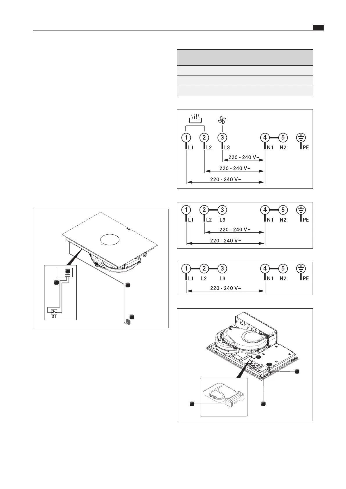
With the optional Home In accessory module PUHIM
(12 V/35 mA), upgrade to an interface for external
devices (e.g. window contact switch) is possible.
1
2
3
4
Fig. 6.46 Connection diagram with optional Home In module
[1] Cooktop and cooktop extractor power supply cable
[2] Power supply
[3] Home In module PUHIM (not included in scope of delivery)
[4] Home In connection cable
[S1] External switch contact
XX
Switch off the main switch/automatic circuit breaker before
connecting the cooktop.
XX
Secure the main switch/automatic circuit breaker against
being switched back on without permission.
XX
Make sure the power to the appliance is disconnected.
XX
Connect the cooktop exclusively via a fixed connection to an
H 05 VV-F power supply cable with corresponding minimum
cross-section (see tab. Fuse protection and minimum cross-
section).