EN
31
Installation
www.bora.com
6.7.5 Preparing the cooktop
Attaching the sealing tape
2
1
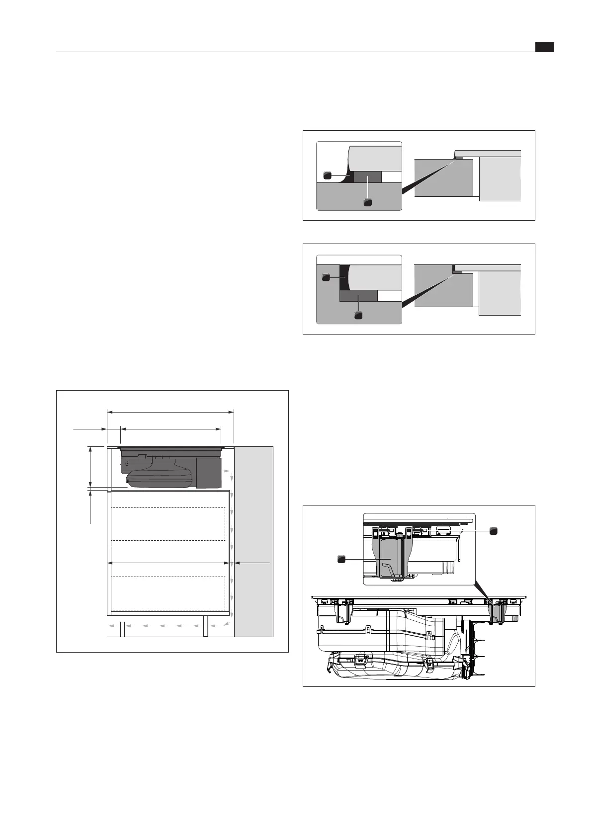
Fig. 6.31 Sealing tape in the case of surface mounting
1
2
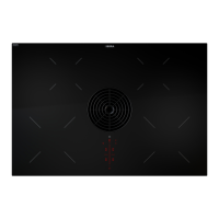
Fig. 6.32 Sealing tape in the case of ush installation
[1] Black, heat-resistant silicone sealant
[2] Sealing tape
XX
In the case of surface mounting, attach the enclosed sealing
tape [2] around the outer edges of the underside of the
cooktop. Do not leave any gaps.
XX
In the case of flush installation, attach the enclosed sealing
tape [2] to the horizontal cutting edge in the worktop cut-out,
even if you are sealing the cooktop with a silicone sealing
compound[1] or similar.
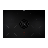
Fitting the installation clamps
1
2
Fig. 6.33 Fitting the installation clamps
[1] Retaining brackets
[2] Installation clamps
i
2 installation clamps must be fitted to each side of the
cooktop.
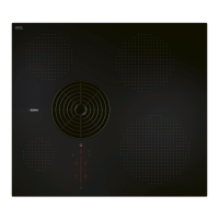
6.7.4 Preparing kitchen units for installation
variant B (floor unit with false floor
under the cooktop)
XO
Cross bars on the kitchen unit in the area of the worktop cut-
out may need to be removed.
XO
In the case of thin worktops, there must be a sufficiently rigid
support plate on the unit.
XO
A false floor must be provided for under the cooktop:
XO
It must be fitted in such a way that it can be removed for
maintenance work.
XO
To ensure sufficient cooktop ventilation, a minimum
distance of 15 mm to the bottom edge of the cooktop is
to be observed.
XO
The back wall of the unit must be flush with the false floor so
that the recirculating air is not directed into the front of the
unit.
XO
A minimum clearance of 25 mm between the back wall of
the unit and an adjacent kitchen unit or room wall must be
observed for the return flow of the recirculated air.
XO
The drawers and/or shelves in the floor unit must be
removable.
XO
For correct installation, the drawers of the floor unit must be
shortened depending on the installation situation.
Installation dimensions
max. 575
199
min. 25
min. 600
min. 50 495
min. 15
Fig. 6.30 Installation dimensions for recirculation installation
variant B, depth of worktop 600 mm
Adjusting the back wall of the unit
XX
Adapt the back wall according to the required installation
dimensions.
XX
If necessary, move the back wall.
XX
Adjust the height of the rear wall to the false floor so that they
are flush with one another.