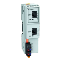
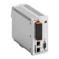
Hall sensor box SHL02.1 (12 V supply voltage)
See the connection diagram for how to connect the Hall sensor box SHL02.1.
Connection diagram
VCC_Encoder +12 V
Fig. 8-13: Connection diagram Hall sensor box SHL02.1
Power supply
12 V (the voltage is made available via the EC interface)
Technical specification of the power supply: See chapter "12 V power supply"
on page 92
Cable length
The maximum allowed cable length depends on several factors: See chapter
8.1.4 "Encoder cable length" on page 94
Specific technical features
For detailed information on the Hall sensor box SHL02.1, see the Func‐
tional Description
"Rexroth Hall sensor box SHL02.1" (R911292537).
DOK-INDRV*-CXX02******-PR03-EN-P Bosch Rexroth AG 91/143
IndraDrive Control Sections CSB02, CSE02, CSH02, CDB02
Technical data - functions
Courtesy of CMA/Flodyne/Hydradyne ▪ Motion Control ▪ Hydraulic ▪ Pneumatic ▪ Electrical ▪ Mechanical ▪ (800) 426-5480 ▪ www.cmafh.com

 Loading...


