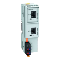
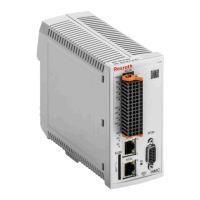
7.7 X38, analog inputs/outputs (DA option)
View Connec‐
tion
Signal name Function Connec‐
tion
Signal name Function
1.1 GND_AnaEA GND reference 2.1 IA_2+ Analog input
1.2 OA_1 Analog output 2.2 IA_2-
1.3 GND_100_An
aOut
GND reference of
analog output
2.3 GND_100_An
aIn
GND reference of
analog input
1.4 OA_2 Analog output 2.4 IA_1+ Analog input
1.5 GND_AnaEA GND reference 2.5 IA_1-
Spring terminal (con‐
nector)
Unit min. max.
Connection cable
Stranded wire
mm
2
0.2 1.5
AWG 24 16
Stripped length mm - 10
Tab. 7-8: Function, pin assignment, properties
Shield connection
chapter 9.3 "Analog inputs/outputs: Shield connection" on page 130
Technical data
● chapter 8.8 "Analog Voltage Input" on page 123
● chapter 8.9 "Analog Current Input" on page 124
● chapter 8.10 "Analog Output" on page 125
Bosch Rexroth AG DOK-INDRV*-CXX02******-PR03-EN-P70/143
IndraDrive Control Sections CSB02, CSE02, CSH02, CDB02
Optional connection points
Courtesy of CMA/Flodyne/Hydradyne ▪ Motion Control ▪ Hydraulic ▪ Pneumatic ▪ Electrical ▪ Mechanical ▪ (800) 426-5480 ▪ www.cmafh.com

 Loading...


