100-214-276 Rev. 3 4-13
2000X aed Actuator Chapter 4: Installation and Setup
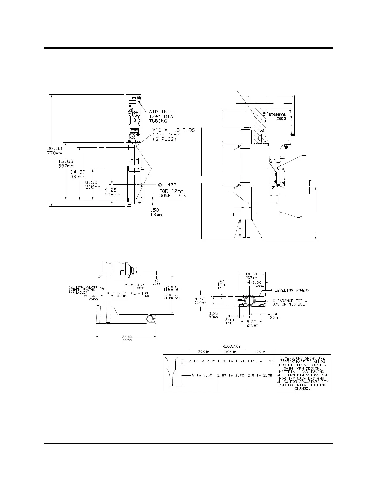
Instruction Manual Installation Requirements
Figure 4.7 2000X Actuator Dimensional Drawing
machined mounting
surfaces (3 places)**
**These three mounting surfaces are flat
within 0.004 in. (0.1mm) TIR, in a tolerance
zone of 16 x 3.5 in. (410 x 90 mm). The
surface to which the actuator is mounted
must also have the same flatness tolerance.
SECTION A-A
BASE (OPTIONAL)
54 mm
70 mm
127 mm
140 mm
33 mm 39 mm
75 mm
24 mm
97 mm
18 mm
64 mm
70 mm
HORN WIDTH AND LENGTH WILL VARY WITH EACH DESIGN
A
A
1092mm
43.0
ø
102 m m
4. 00
31 mm
12. 7
9
mm
3.
4.5min
114 m m m i n
28.0max
711mmmax
13mm
.5 0
343mm
13.5 2
242 mm
16.70
250mm
9.82
5.00
127mm
472mm
18 .59
SPACE ALLOCATION FOR
CONNECTORAND CABLE BENDS
40"LONGCOLUMN
(OTHER LENGH TS
AVAILABLE)
OF
HORN
ENCODER FOR
AED ONLY
5
4
3
75
DOC EXPIRES 12PM 7/24/2012. Article or Material must comply with the requirements
stipulated by RoHS in its current version