4-28 100-214-276 Rev. 3
Chapter 4: Installation and Setup
Installation Steps
Ensure all unused wires are properly isolated. failure to do so may result in Power Supply or
system failure.
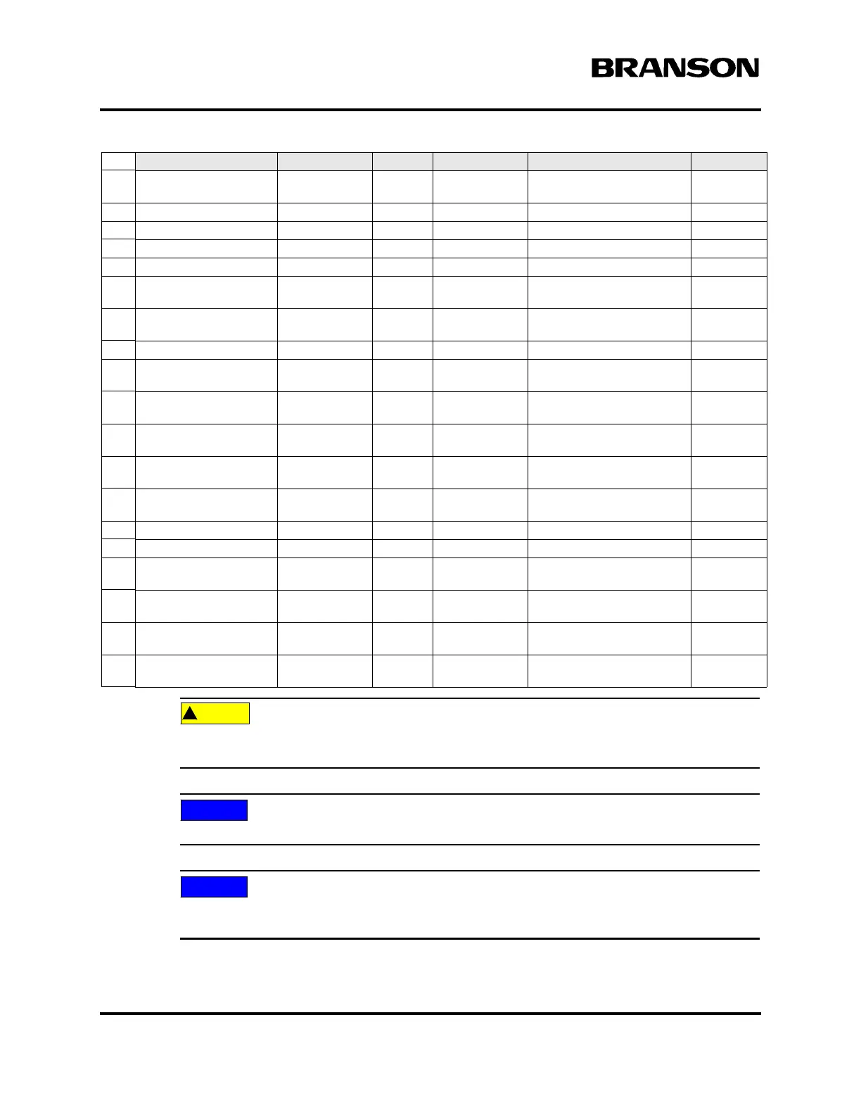
User can change 24V Logic 0 True to 1.
Refer to the Branson Automation Guide (EDP 100-214-273) for additional information about
selection and use of Input and Output features listed in the following Table.
43 READY_ RELAY_1 Relay Contact Output 40V, 0.25A Contact Closure Blu/Orn/
Red
15 READY_RELAY_2 Relay Contact Output 40V, 0.25A Contact Closure Orn/Grn
26 RUN Open Collector Output 24V, 25mA max Run signal send to PS Orn/Blk/Grn
39 SEEK Open Collector Output 24V, 25mA max Seek Signal send to PS Wht/Blk/Blu
4 SOL_VALVE_SRC 24V Output 0/24V, 125mA SV1 Source Orn/Blk
16 SOL_VALVE_RTN 24V Return Input 0V SV1 Return Blk/Wht/
Red
20 SUSPECT_PART 24V Logic 0
True
Output 0/24V, 100mA Orn/Blk/
Wht
10 USER_AMP_IN Analog Input -10V to +10V User Amplitude control signal Blk/Red
25 USER_FREQ_OFFSET Analog Input -10V to +10V User Freq. offset control sig-
nal
Grn/Blk/Orn
35 WELD_ON 24V Logic 0
True
Output 0/24V, 100mA Start of sonics and trigger Grn/Wht/
Blu
30 WELD_ON_RELAY_1 Relay Contact Output 40V, 0.25A Contact Closure Orn/Wht/
Blu
44 WELD_ON_RELAY_2 Relay Contact Output 40V, 0.25A Contact Closure Blk/Orn/
Red
23 +10V_REF Analog Output 10.0V 10VDC ref. voltage from PS Wht/Red/
Grn
12 24V_RTN 24V Ground Input 0V 24V Return Orn/Red
13 24V_SRC 24V Source Output 24V, 1.25A max 24V Source Blu/Red
27 24V_RTN 24V Ground Input 0V 24V Return Blu/Wht/
Orn
28 24V_SRC 24V Source Output 24V, 1.25A max 24V Source Blk/Wht/
Orn
41 24V_RTN 24V Ground Input 0V 24V Return Grn/Orn/
Red
42 24V_SRC 24V Source Output 24V, 1.25A max 24V Source Orn/Red/
Blu
Pin
Signal Name Signal Type Direction Signal Range Definition Colors
DOC EXPIRES 12PM 7/24/2012. Article or Material must comply with the requirements
stipulated by RoHS in its current version