BRAKE
KUKJE MACHINERY CO., LTD.
120
5. CHECKING, DISASSEMBLING AND SERVICING
<3> SERVICING
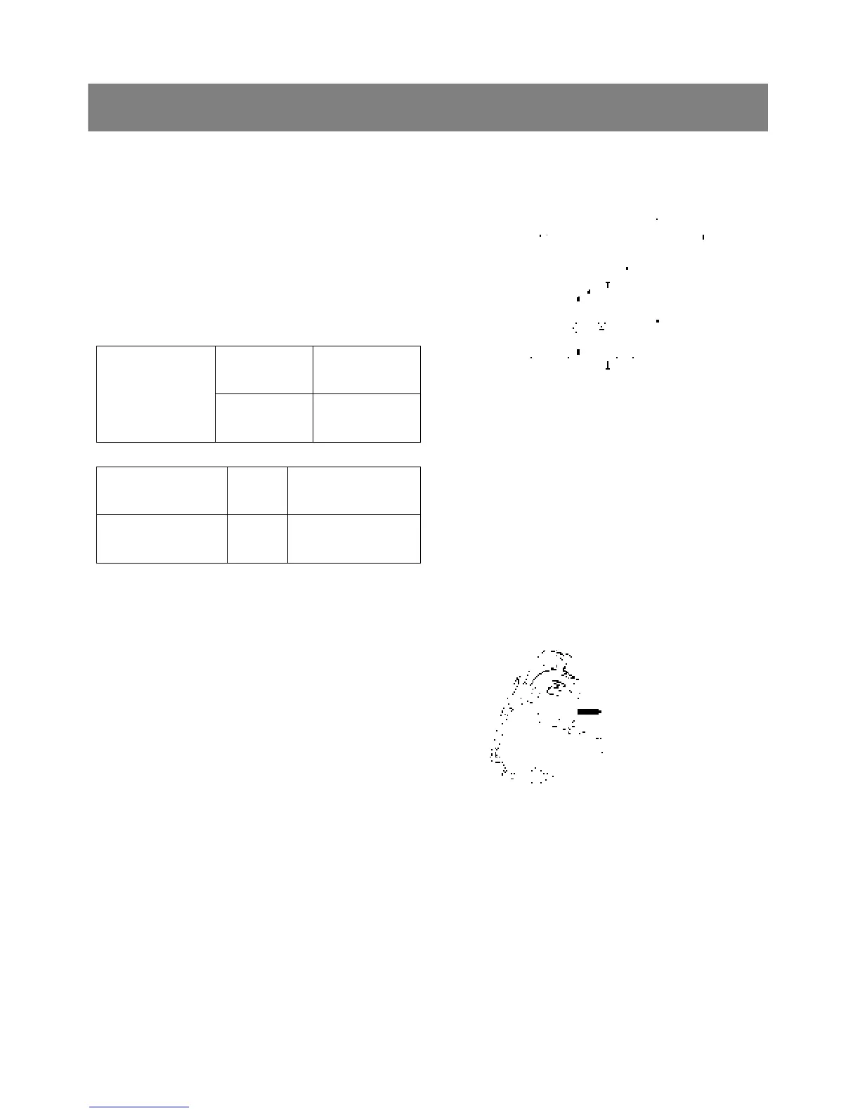
*. PART NAME
1) Brake pedal shaft 2) Center frame
3) Bush
A) Bush I.D. B) Brake pedal shaft O.D.
< Clearance between brake pedal shaft and center
frame bush >
1. Measure the brake pedal shaft O.D. with an
outside micrometer.
2. Measure the bush(3) I.D. with a cylinder gauge.
3. If the clearance exceeds the allowable limit,
replace it.
Factory spec.
0.0 to 0.165 mm
0.0 to 0.00649 in.
Clearance between
brake pedal shaft
and center frame
bush
Allowable limit
1.0 mm
0.0039 in.
Brake pedal shaft O.D.
Factory
spec.
24.067 to 25.030 mm
0.98295 to 0.98543 in.
Center frame bush I.D.
Factory
spec.
25.030 to 25.081 mm
0.98543 to 0.98744 in.
< Brake cam lever movement >
1. Move the brake cam lever by hand to check the
movement.
2. If the movement is heavy, refine the brake cam
with sand-paper.
< Cam plate flatness and bearing holder wear >
1. Place a straightedge of 150mm(5.91 in.) or more
in length on the contacting surface of the cam
plate and the bearing holder.
2. Inspect the friction surface of the cam plate and
the bearing holder with the straightedge, and
determine if a 0.30mm(0.0118 in.) feeler gauge
will fit on the part of wear.
3. If it will fit, resurface.