HYDRAULIC SYSTEM
KUKJE MACHINERY CO., LTD.
147
4. CHECKING, DISASSEMBLING AND SERVICING
3) Hydraulic Cylinder and Control Valve
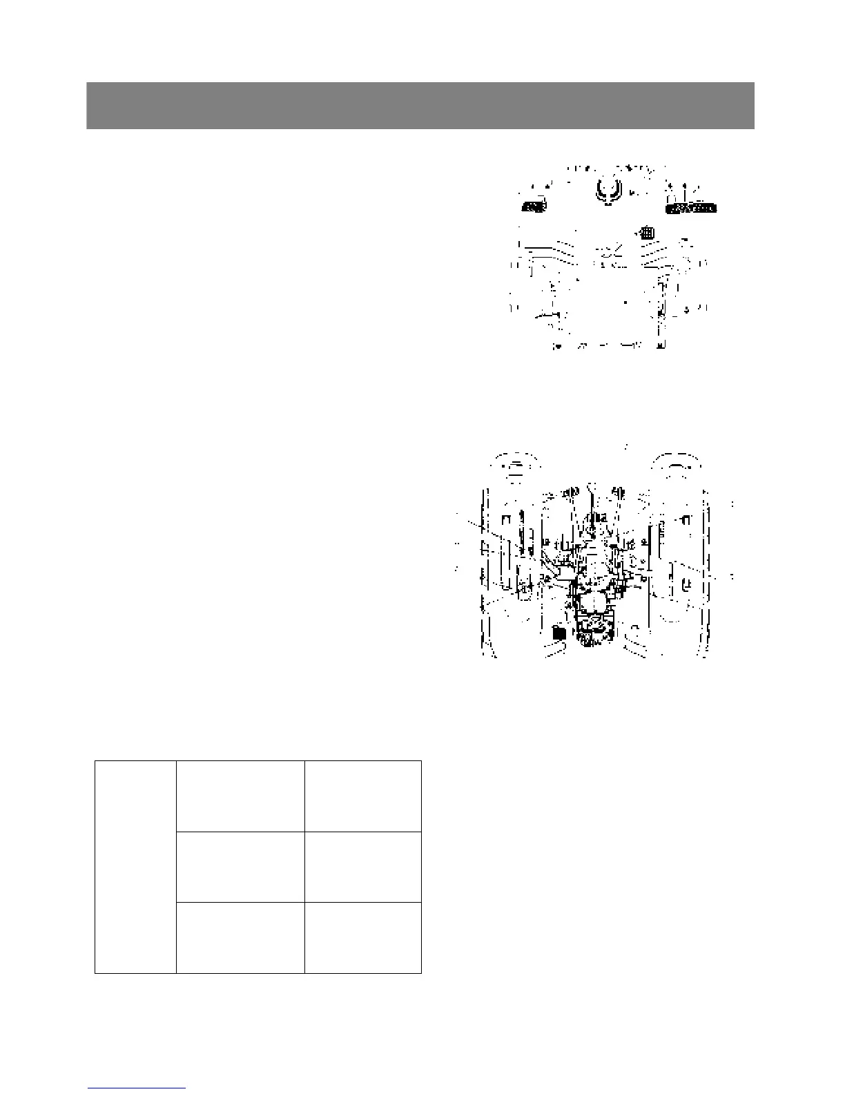
< Seat and seat stay >
1. Remove the seat.
2. Remove the lowering speed adjusting knob and
dipstick, then remove the seat under cover.
3. Remove the tool box(3).
4. Disconnect the 2P connectors from the seat
switches, and then remove the seat stray(1).
5. Disconnect the wiring harness.
*. PART NAME
1) Seat stay 2) Seat
3) Tool box
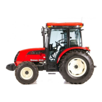
< Hydraulic cylinder assembly >
1. Remove the top link and disconnect the lift rods.
2. Remove the all lever grip and remove the both
lever guides(2),(8).
3. Disconnect the differential lock rod(1) and remove
the hydraulic control lever(3).
4. Disconnect the delivery pipe for 3point hitch(4).
5. Remove the top link bracket(6) and connecting
plate mounting screws.
6. Remove the hydraulic cylinder assembly(5) with
connecting plate.
▷ Reassembling
9 Apply liquid gasket to joint face of the differential
case and the hydraulic cylinder.
Connecting plate
Mounting screw
48.1 to 55.9 N·m
4.9 to 5.7 kgf·m
35.4 to 41.2 ft-lbs
Hydraulic cylinder
mounting screw
and nut
48.1 to 55.9 N·m
4.9 to 5.7 kgf·m
35.4 to 41.2 ft-lbs
Tightening
torque
Delivery pipe
joint bolt
33.3 to 38.2 N·m
3.4 to 3.9 kgf·m
24.6to28.2ft-lbs
*. PART NAME
1) Differential lock rod 2) Lever guide RH
3) Hydraulic control lever 4) Delivery pipe
5) Hydraulic cylinder 6) Top link bracket
7) Connecting plate 8) Lever guide LH
(3)
(1)
(2)