HYDRAULIC SYSTEM
KUKJE MACHINERY CO., LTD.
148
4. CHECKING, DISASSEMBLING AND SERVICING
*. PART NAME
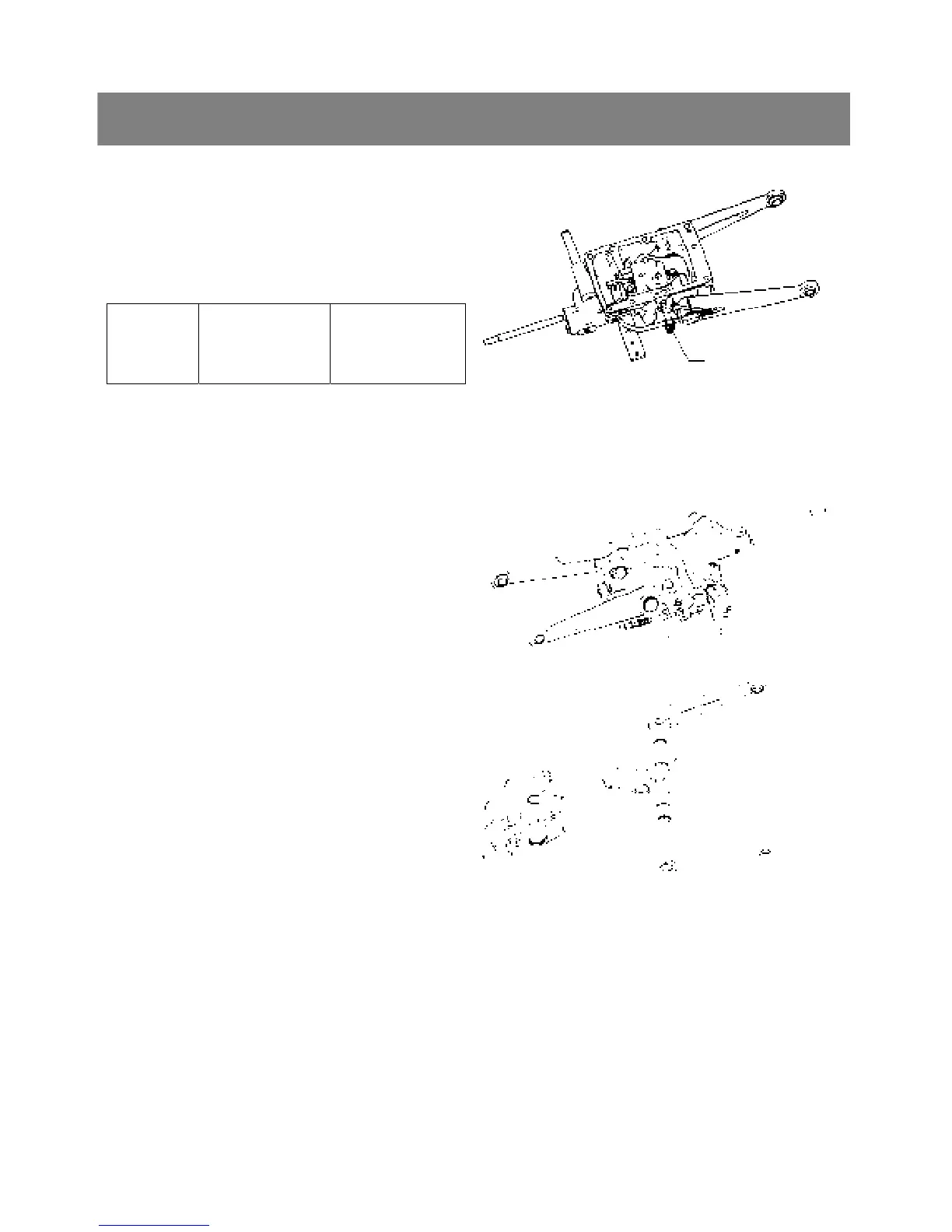
1) Control valve
< Control valve >
1. Remove the control valve mounting screws, and
remove the control valve(1).
▷ Reassembling
9 Take care not to damage the O-ring.
Tightening
torque
Cover mounting
screw
23.6 to 27.4 N·m
2.4 to 2.8 kgf·m
17.4 to 20.2 ft-lbs
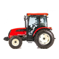
< Lift arm, hydraulic arm shaft and hydraulic arm>
1. Remove the feedback rod lock nuts(5) and
spring(6).
2. Remove the lift arm LH(1).
3. Remove the hydraulic arm shaft(3) and lift arm
RH(2) as a unit.
▷ Reassembling
9 Align the alignment marks(7) of the hydraulic
arm and hydraulic arm shaft.
9 Align the alignment marks(7) of the lift arm LH
and hydraulic arm shaft.
9 Apply grease to the right and left bushings and
O-rings.
9 Take care not to damage the O-rings.
*. PART NAME
1) Lift arm LH 2) Lift arm RH
3) Hydraulic arm shaft 4) Feedback rod
5) Lock nut 6) Spring
7) Alignment mark
(1)