FRONT AXLE
KUKJE MACHINERY CO., LTD.
59
4. CHECKING, DISASSEMBLING AND SERVICING
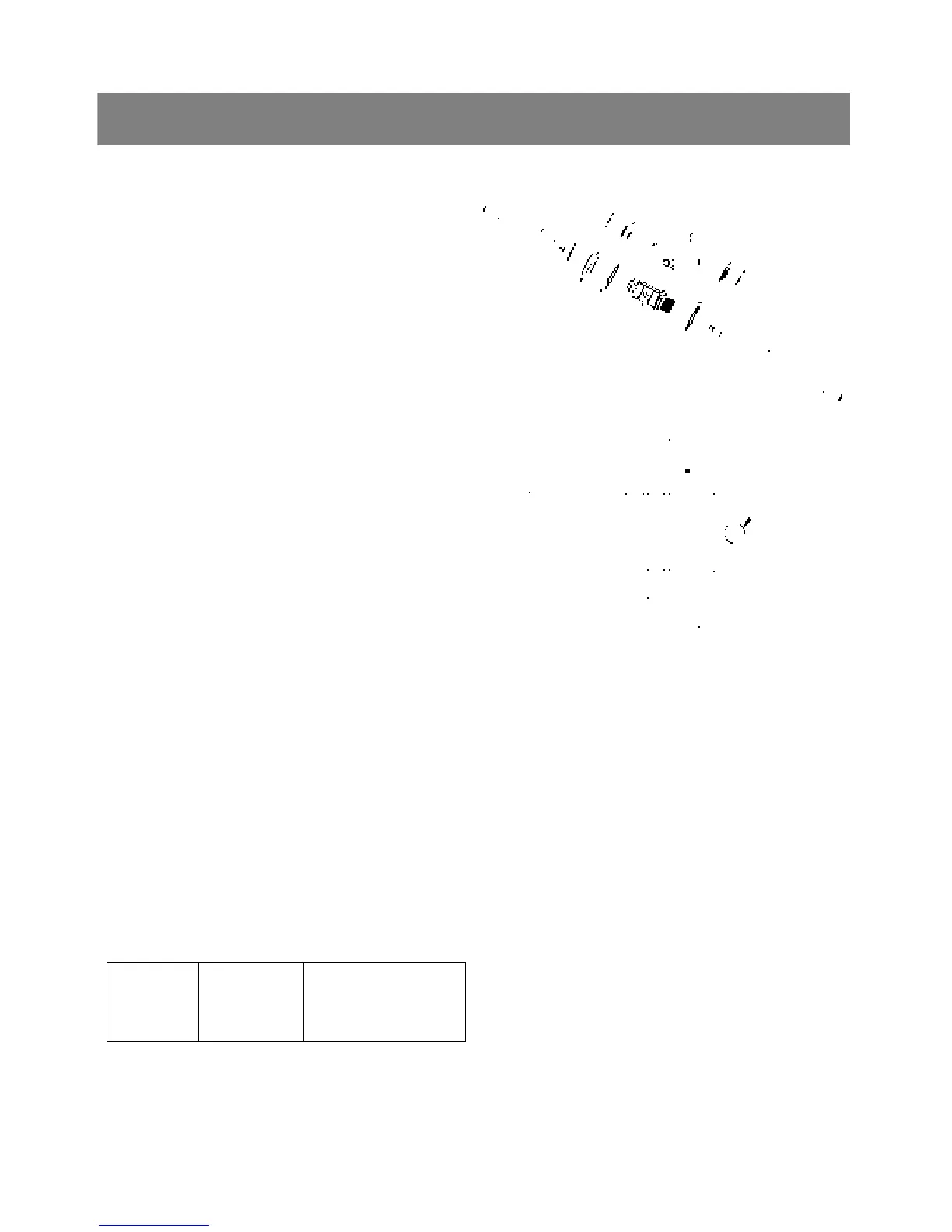
< Differential gear >
1. Tap out the spring pins(5) and remove the
external snap ring(2), and then pull out both of
the differential yoke shafts(1),(9).
2. Remove the differential side gears(4).
3. Remove the differential pinions(6).
4. Remove the spiral bevel gear(8), and
bearings(7),(11).
▶ NOTE
1) Arrange the parts to their original position.
▷ Reassembling
9 Apply molybdenum disulfide to the inner
circumferential surface of the differential side
gears(4) and differential pinions(6).
9 Be sure to install the spring pins(5) as shown in
the figure.
*. PART NAME
1) Differential yoke shaft RH
2) External snap ring 3) Thrust collar
4) Differential side gear 5) Spring pin
6) Differential pinion 7) Ball bearing
8) Spiral bevel gear
9) Differential yoke shaft LH
10) Differential case 11) Ball bearing
<3> SERVICING
< Turning torque of spiral bevel pinion shaft >
1. Cramp the spiral bevel pinion shaft assembly to
the vise and tighten the lock nut.
2. Measure the turning torque of bevel pinion shaft.
3. If the turning torque is not within the factory
specifications, adjust with the lock nut.
Tightening
torque
Factory spec.
0.8 to 1.0 Nm
0.08 to 0.10 kgfm
0.59 to 0.73 ft-lbs
▶ NOTE
1) After turning force adjustment, be sure tighten
the lock nut.
(1)
(2)
(3)
(4) (6)
(5)
(6)
(7)
(8)
(4)
(3)
(9)
(11)
(10)
(4)
(5)