FRONT AXLE
KUKJE MACHINERY CO., LTD.
58
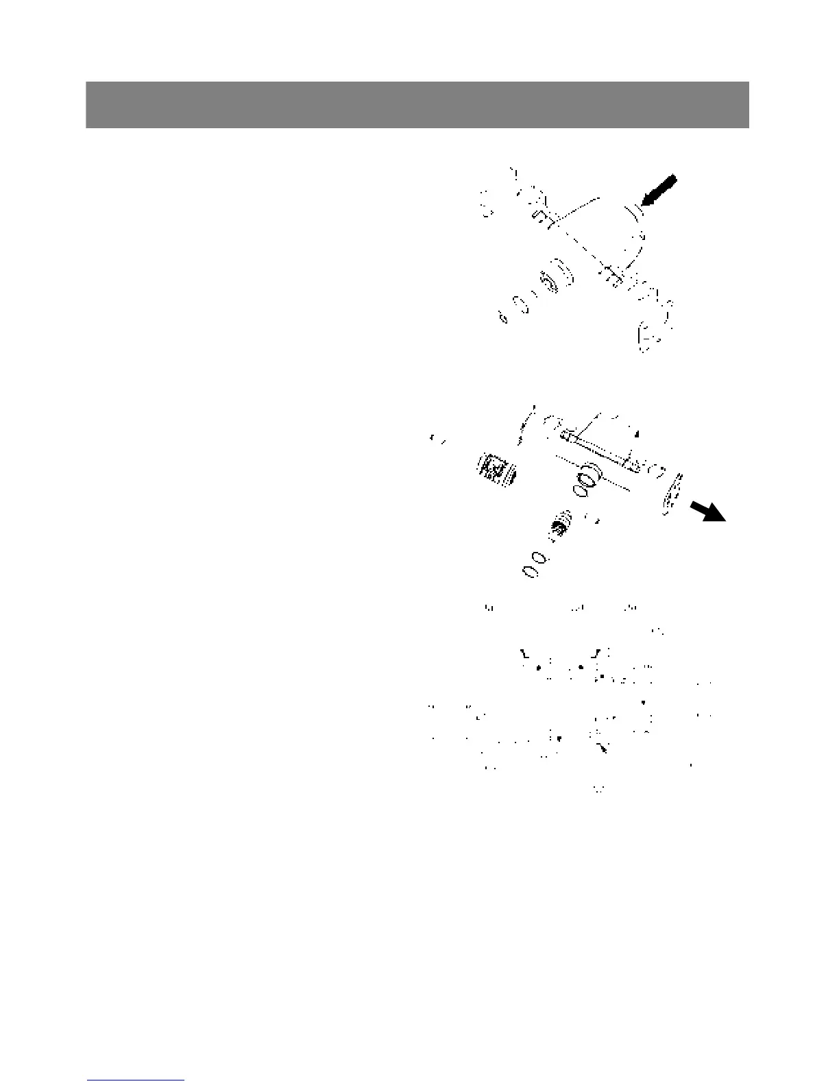
4. CHECKING, DISASSEMBLING AND SERVICING
< Spiral bevel pinion shaft and differential gear
assembly >
1. Remove the internal snap ring(1).
2. Tap put the spiral bevel pinion shaft(2) by the
brass rod and hammer.
3. Take out the differential gear assembly(3) with
differential yoke shafts, from right side of front
axle case(4).
4. Remove the lock nut(7).
5. Remove the taper roller bearings(6).
▷ Reassembling
9 Apply gear oil to the taper roller bearings(6) and
install them correctly, nothing their direction.
9 Replace the lock nut(7) with new ones.
9 After tightening the lock nut(7).
9 Install the adjusting collars(5) to their original
position.
▷ Reference
9 Thickness of adjusting collars :
3.4mm (0.134in.)
3.6mm (0.142in.)
3.8mm (0.150in.)
3.9mm (0.154in.)
4.0mm (0.157in.)
4.1mm (0.161in.)
4.2mm (0.165in.)
4.4mm (0.173in.)
4.5mm (0.177in.)
4.6mm (0.181in.)
*. PART NAME
1) Internal snap ring 2) Spiral bevel pinion shaft
3) Differential gear assembly
4) Front axle case 5) Adjusting collar
6) Taper roller bearing 7) Lock nut
8) Collar
(3)
(4)
(2)
(5)
(1)