FRONT AXLE
KUKJE MACHINERY CO., LTD.
55
4. CHECKING, DISASSEMBLING AND SERVICING
2) Disassembling Front Axle
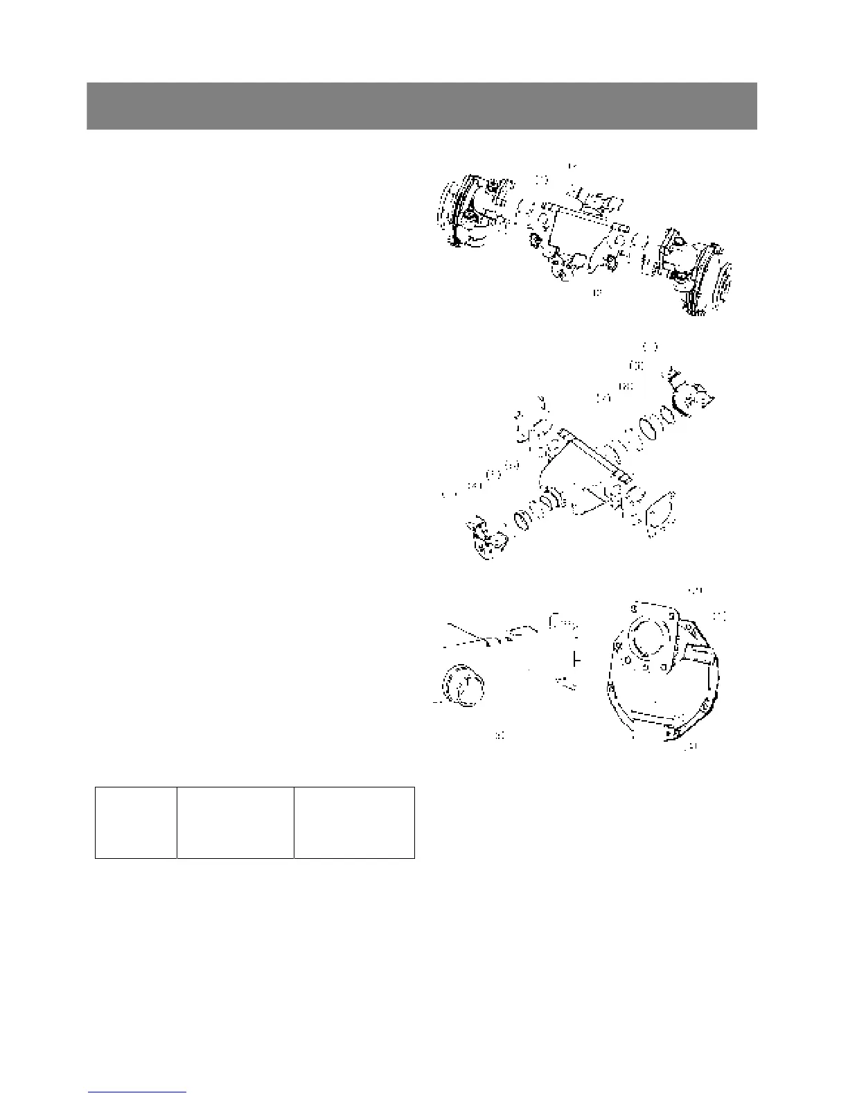
< Tie-rod and axle bracket >
1. Remove the slotted nut and remove the tie-
rod(3).
2. Remove the front axle brackets(1),(2).
▷ Reassembling
9 Apply grease to the thrust collars(4),(9), o-
ring(6),(7) and oil seal(10).
9 After tightening the slotted nut to the specified
torque, install the cotter pin as shown in the
figure.
*. PART NAME
1) Assy holder(F) 2) Assy holder(R)
3) Tie-rod 4) Thrust collar
5) Bushing 6) O-ring
7) O-ring 8) Bush
9) Thrust collar 10) Oil seal
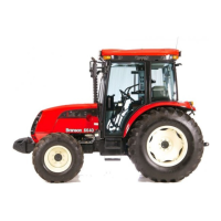
< Bevel gear case and front gear case >
1. Remove the bevel gear case mounting screws.
2. Remove the bevel gear case(1) and front gear
case(4) as a unit from the front axle case(3).
▷ Reassembling
9 Apply grease to the O-ring(2) and take care not
to damage it.
9 Do not interchange right and left bevel gear case
assemblies and right and left gear case
assemblies.
Tightening
torque
Bevel gear case
mounting screw
77.5 to 90.1 Nm
7.9 to 9.2 kgfm
57.1 to 66.5 ft-lbs
*. PART NAME
1) Bevel gear case 2) O-ring
3) Front axle case 4) Front gear case RH