FRONT AXLE
KUKJE MACHINERY CO., LTD.
61
4. CHECKING, DISASSEMBLING AND SERVICING
*. PART NAME
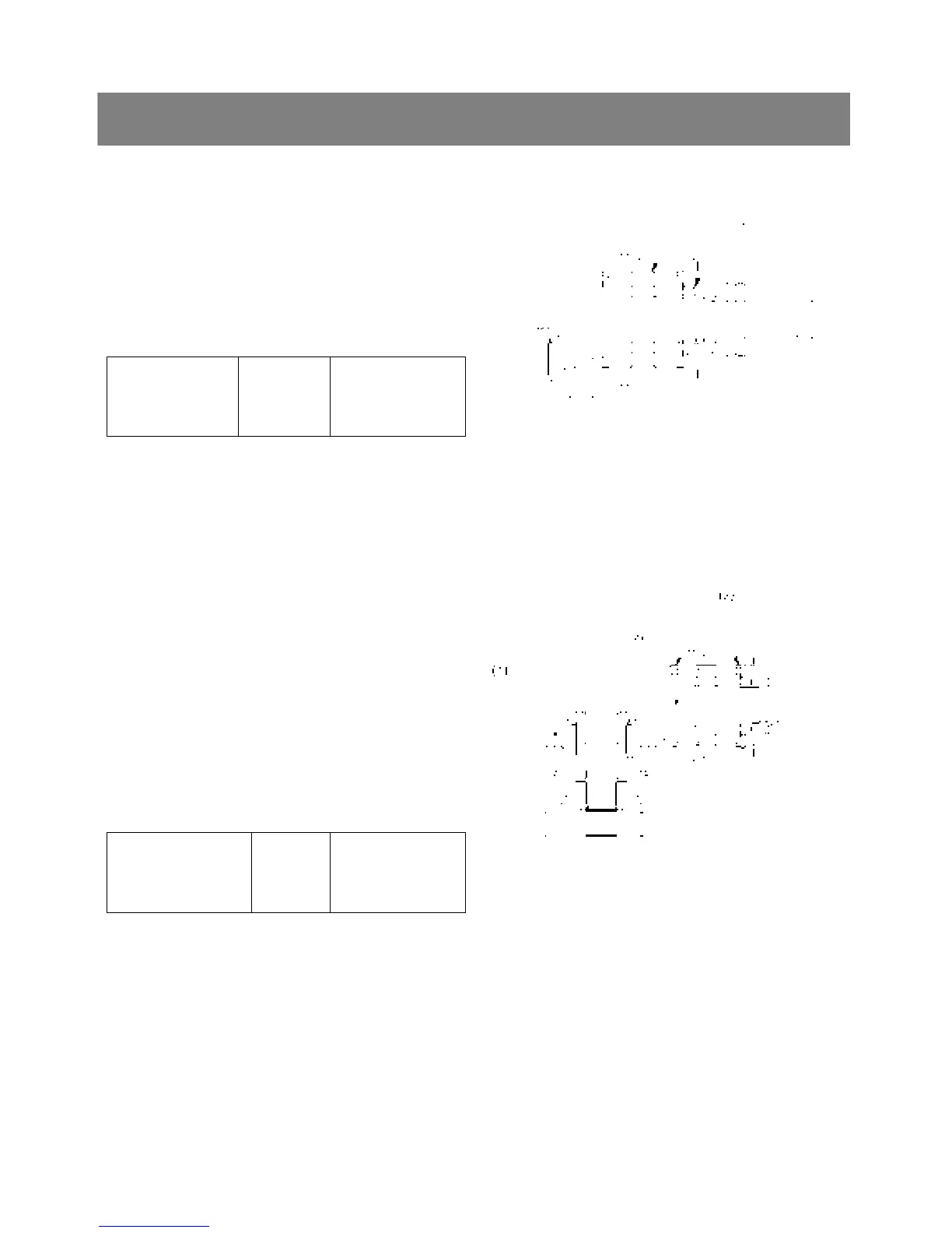
1) Collar 2) Lock nut
< Turning torque of spiral bevel pinion shaft >
1. Install the spiral bevel pinion shaft assembly only
to the front axle case.
2. Measure the turning torque of the spiral bevel
pinion shaft.
3. If the turning torque is not with in the factory
specifications, adjust with lock nut.
Turning torque of
spiral bevel pinion
shaft
Factory spec.
0.8 to 1.0 Nm
0.08 to 0.10 kgfm
0.59 to 0.74 ft-lbs
▶ NOTE
1) After turning torque adjustment, be sure tighten
the lock nut.
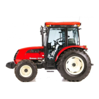
< Backlash between spiral bevel pinion shaft and
spiral bevel gear >
1. Set a dia gauge(lever type) with its finger on the
spline of spiral bevel pinion shaft.
2. Measure the backlash be moving the spiral bevel
pinion shaft by hand lightly.
3. If the backlash is not within the factory
specifications, select the adjusting collar(3).
4. Adjust the backlash properly by repeating the
above procedures.
Backlash between spiral
bevel pinion shaft and
spiral bevel gear
Factory
spec.
0.1 to 0.3 mm
0.004 to 0.012 in.
▷ Reference
9 Above factory specification should be measured
on the tooth of spiral bevel pinion. When
measuring the backlash on the spline of its shaft,
factory specification will be 0.0571 to 0.1714mm
(0.00225 to 0.00675 in.)
9 Thickness of adjusting collars :
3.4mm(0.134in.), 3.6mm(0.142in.)
3.8mm(0.150in.), 3.9mm(0.154in.)
4.0mm(0.157in.), 4.1mm(0.161in.)
4.2mm(0.165in.), 4.4mm(0.173in.)
4.5mm(0.177in.), 4.6mm(0.181in.)
*. PART NAME
1) Spiral bevel gear 2) Spiral bevel pinion shaft
3) Adjusting collar