TRANSMISSION
KUKJE MACHINERY CO., LTD.
97
4. CHECKING, DISASSEMBLING AND SERVICING
*. PART NAME
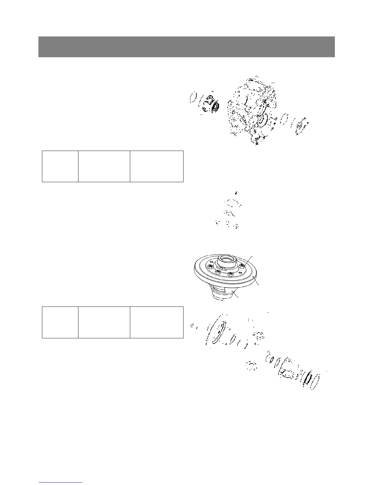
1) Bearing holder 2) Adjusting shim
3) Differential gear assembly
< Differential gear assembly >
1. Remove the bearing holder mounting screws and
remove the bearing holder(1).
2. Take out the differential gear assembly(3).
▷ Reassembling
9 Install the differential gear assembly, noting the
number of shims(2) in the differential case left
side and bearing holder side.
Tightening
torque
Differential gears
bearing holder
mounting screw
23.5 to 27.5 Nm
2.4 to 2.8 kgfm
17.4 to 27.3 ft-lbs
< Bearing >
1. Remove the right and left bearings from in the
differential case.
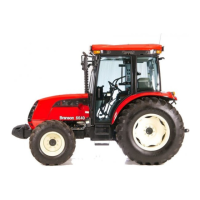
< Spiral bevel gear >
1. Remove the spiral bevel gear UBS screws(1).
2. Remove the spiral bevel gear(2) from differential
case(3).
▷ Reassembling
9 Apply liquid lock to the spiral bevel gear UBS
screws.
Tightening
torque
Spiral bevel gear
UBS screw
29.4 to 34.3 Nm
3.0 to 3.5 kgfm
21.7 to 25.3 ft-lbs
< Differential side gear and differential pinion >
1. Put parting marks on the differential
pinion(1) and the differential side gear(2).
2. Tap out the dowel pin(3).
3. Remove the differential pinion shaft.
4. Remove the differential pinion(4), differential
side gear(2) and shim(5).
▷ Reassembling
9 Install the differential pinion and differential side
gear, aligning the parting marks.
*. PART NAME
1) Spiral bevel
gear UBS screw
2) Spiral bevel gear
3) Differential case
*. PART NAME
1) Differential pinion 2) Differential side gear
3) Dowel pin 4) Differential pinion
5) Shim
(2)
(3)
(2)
(1)
(1)
(2)
(3)