Do you have a question about the Braun perfusor compact and is the answer not in the manual?
Details on who is authorized to perform service work and their qualifications.
User's obligation for safety checks and recommendations for training.
Manual version state and B. Braun's right to make technical modifications.
Conditions for inclusion in revision service: training or order.
Conditions under which the manufacturer is responsible for safety and performance.
B. Braun's certification for quality management (ISO 9001, ISO 13485).
Training is required; ESD standards must be observed. Device check after repair.
Information on electrostatic discharge damage to components and potential malfunctions.
Use original spare parts; service personnel responsible for test equipment calibration.
Notes, cautions, and warnings are set off as follows: Note, CAUTION, WARNING.
Abbreviations used in the manual are listed with their definitions.
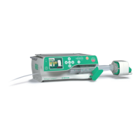
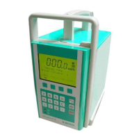
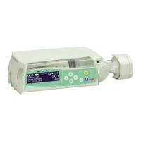
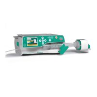
Description of the Perfusor compact's physical components and design.
Details the Perfusor compact's electronic components: A-Module, E-Module, Drive unit.
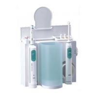
Lists accessories like connecting leads and pole clamps with order numbers.
Table listing approved software versions and hardware identification.
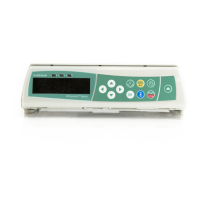
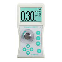
Procedure to display software and hardware versions on unit startup.
Procedure for extended version display showing operating hours and maintenance interval.
Table listing LC display error codes and their descriptions.
Lists compatible unit software versions with service program versions and order numbers.
Overview of the Service Program's user-friendly PC interface and authorized use.
Step-by-step guide for installing the Service Program software on a PC.
Instructions for removing the Service Program software from the PC.
Steps to select language, interface, and screen display in the Service Program.
Procedure for connecting the unit to the PC and starting communication.
Instructions to read, display, and save unit settings using the Service Program.
Procedure for adjusting unit settings such as service values and calibration.
General steps and specific calibration procedures (serial number, length, pressure).
Information on the Default.dat file and adjusting factory settings.
Troubleshooting steps for communication issues with the pump.
Explanation of the menu structure and commands in the Service Program.
Details on EEPROM menu functions: Read, Default, and Write.
Options for calibration: Serial number, Length calibration, Pressure calibration, Overload check.
Description of Service Menu: Service Values and Processing values, logging alarms.
Options for selecting syringe types: Table, Free type, OPS.
Options for setting Service interval and other constants.
Step-by-step checks after using the Service Program for modifications.
Checklist for verifying settings after Service Program operations.
General repair information, battery handling, and fitting plastic screws.
Information on exchanging the syringe table and quick reference guide.
Procedure for exchanging the syringe holder.
Instructions for turning or exchanging the unit feet.
Procedure for exchanging the battery compartment cover.
Procedure for exchanging the snap-in clip and lever.
Procedure for exchanging the A-Module and its components.
Procedure for exchanging the LS-clip and setting alarm tone loudness.
Procedure for exchanging the E-Module, including preparation and calibration.
Procedure for exchanging the N-Module (220-240 V or 100-120 V).
Procedure for exchanging the housing upper part including keyboard and handle.
Procedure for exchanging the carrying handle.
Procedure for exchanging the complete drive unit, including safety warnings.
Procedure for exchanging the axial positioner, including calibration.
Procedure for exchanging the drive board, including cable layout and caution.
Procedure for exchanging the drive head, including tamper-proof caps.
Procedure for exchanging the housing bottom part and shifting type plates.
Checklist covering visual, electrical safety, and functional inspection.
Detailed steps for visual inspection of unit components during TSC.
Steps for functional checks including unit startup, alarms, and operation.
Procedures for pump operation during checks, including calibration gauge use.
Procedure for checking pressure cut-off stages with caution and warning notices.
Procedure for checking syringe recognition with calibration gauges.
Procedure for testing pre-alarm and end alarm functions with syringes.
Procedure for measuring voltage, resistance, and leakage current.
Requirement for a Technical Safety Check every 24 months.
Checklist for routine technical safety checks of the Perfusor compact.
Detailed steps for visual inspection of unit components during TSC.
Steps for functional inspection, including unit startup, alarms, and operation.
Procedure for checking pressure cut-off stages with caution and warning notices.
Steps for checking syringe selection and recognition.
Procedure for measuring voltage, resistance, and leakage current.
Instructions for entering rate and bolus rate limitations in TSC.
Details on revisions of the Service Manual, including changes made.
List of pages and their corresponding version numbers.
| Brand | Braun |
|---|---|
| Model | perfusor compact |
| Category | Medical Equipment |
| Language | English |