16 Brocade MLX Series and NetIron XMR Hardware Installation Guide
53-1003821-01
Router modules
1
Brocade MLX and NetIron XMR models support one port only.
The 100xGbE interface module occupies two interface module slots in any chassis, with one slot
active and one slot inactive. In all devices, the lower number of the two occupied slots becomes the
active slot.
Because of the possibility of overheating, 2x100GbE interface modules must not be installed in the
top slot of a Brocade MLX or XMR 4-slot chassis.
Before you install a 2x100GbE module, you will need to remove the center slot guide that divides
the slot into two partitions. Do not discard this guide, as you will need it if you ever want to convert
the slot into two slots. For information about how to remove the center guide and install high-speed
fabric modules, refer to the 2x100GbE module installation instructions in the appropriate
installation chapter for your router model.
Before installing the 100GbE module in a chassis, the tm-credit-size must be changed to 1024
bytes.
You will also need to change the system tm-credit-size to 1024b (which readies the device to
forward 100 Gbps traffic). Log into your system and enter the following commands in the
configuration level of the CLI. Remember to write to memory and reload the device.
Brocade# config
Brocade(config)# system-init tm-credit-size credit_1024b
Brocade(config)# exit
Brocade# write memory
Brocade# reload
The 100GbE module requires a minimum software version of R05.2.00. Please upgrade all software
on the system to a minimum version of R05.2.00 before you install your 2x100G module.
100xGbE modules require high-speed switch fabric modules to operate.
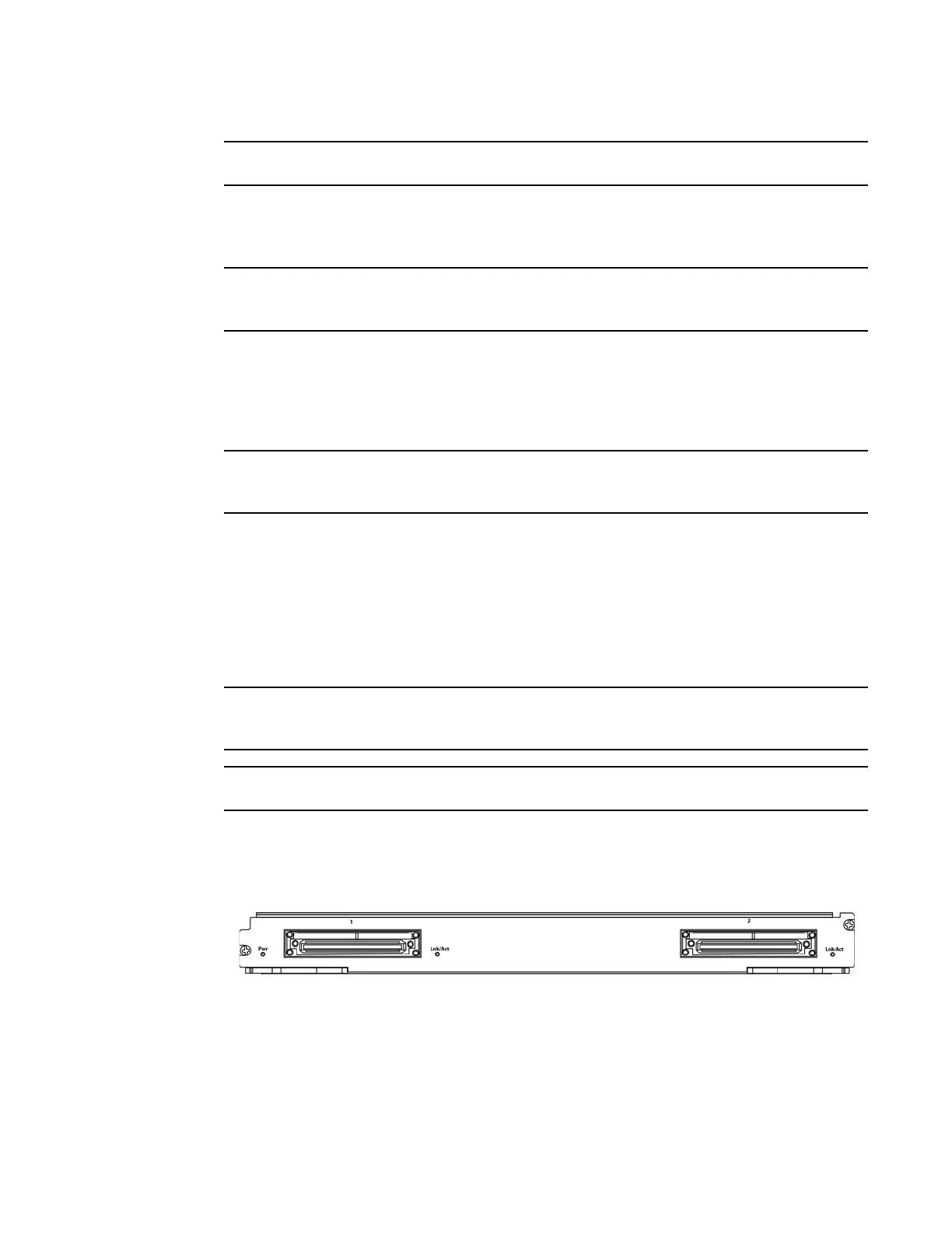
Figure 11 shows the front panel of the 2x100GbE 2-port interface module.
FIGURE 11 100xGbE 2-port interface module front panel
The front panel contains the following features:
• Power LED and Lnk/Act LED for each port (as described in Table 4)
• Two 100xGbE CFP ports
 Loading...
