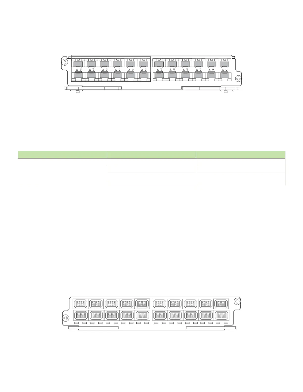
FIGURE 14 BR-MLX-1GFx24-X and BR-MLX-1GFx24-X-ML ber interface module front panel
The front panel includes the following features:
• Arrow-shaped LEDs in center horizontal strip for all ports. LEDs to the left support the top ports, LEDs to the right (pointing
down) support the bottom ports.
• 24 1 Gbps ber ports
The following table describes the port status for the BR-MLX-1GFx24-X and BR-MLX-1GFx24-X ber module.
TABLE 19 BR-MLX-1GFx24-X and BR-MLX-1GFx24-X
ber module LEDs
Position State Meaning
Arrow-shaped LEDs in center horizontal strip
between ports. Left LEDs support upper ports.
Right LEDs support lower ports.
Solid green A link has been established.
Green blinking The port is transmitting and receiving packets.
O No link exists, and the port is not transmitting or
receiving packets.
For a list of SFP optics supported for the BR-MLX-1GFx24-X and BR-MLX-1GFx24-X interface modules, refer to the latest version of
the Brocade Optics Family Data Sheet.
Power supply requirements for BR-MLX-1GFx24-X and BR-MLX-1GFx24-X-ML interface modules
For power supply requirements for BR-MLX-1GFx24 and BR-MLX-1GFx24-X ML (24-port 1 Gbps) ber interface modules, refer to
Hardware specications for Brocade MLXe Series routers on page 271.
20-port 100/1000 Ethernet interface module
The front panel includes the following features:
• LEDs to the left support the top ports, LEDs to the right support the bottom ports
• 20 100/1000 Ethernet SFP ports
FIGURE 15 20-port 100/1000 Ethernet module front panel
The following table describes the port LED status of the 20-port 100/1000 Ethernet module.
Router modules
Brocade NetIron MLXe Series Hardware Installation Guide
53-1004203-04 69

 Loading...