TABLE 20 20-port 100/1000 Ethernet module LEDs
Position State Meaning
Below each Ethernet port.
(Left-side LED supports port in top row. Right-
side LED supports port in bottom row.)
On or blinking The port is transmitting and receiving packets.
O for an extended period The port is not transmitting or receiving packets.
100/1000 Ethernet ports
The 100/1000 Ethernet interface module contains 20 physical ports, through which you can connect your router to other network
routers at a speed of 100 Mbps or 1 Gbps.
You must insert an SFP-compliant ber-optic transceiver (provided by Brocade) into a physical port. SFP-compliant ber-optic
transceivers provide a physical medium-dependent (PMD) ber interface that can be used with either the LAN physical layer (PHY) or
WAN physical layer (WAN PHY).
For a list of SFP optics supported by Brocade, refer to the latest version of the Brocade Optics Family Data Sheet.
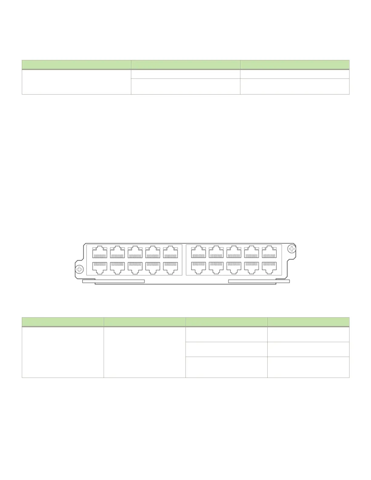
20-port 10/100/1000 Ethernet interface module
The front panel includes the following features:
• LEDs
• Twenty 10/100/1000 copper Ethernet ports.
FIGURE 16 20-port 10/100/1000 copper Ethernet interface module front panel
The following table describes the LED status for the 20-port 10/100/1000 copper Ethernet interface module.
TABLE 21 20-port 10/100/1000 Ethernet module LEDs
LED Position State Meaning
Link or Active Above the ports. The top port LED
is on the left side, the bottom port
LED is on the right side.
On (solid) A link is established with the remote
port (with no trac).
Blinking The port is transmitting and
receiving packets.
O A link is not established with the
remote port and no trac is being
passed.
NI-MLX-1Gx48-T-A interface module
The front panel includes the following features:
• A power LED located below the part number
• Eight mini-RJ21 connectors, each supporting six 10/100/1000 Mbps Ethernet ports
Router modules
Brocade NetIron MLXe Series Hardware Installation Guide
70 53-1004203-04

 Loading...