©2013 Brooks Automation Inc. Pub. No. 8040444, Rev. AA, 01/14/2013 ECO No. 63723 v
Figures
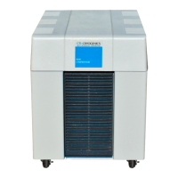
Figure 1-1: 9600 Compressor . . . . . . . . . . . . . . . . . . . . . . . . . . . . . . . . . . . . . . 1-3
Figure 1-2: 9600 Compressor Dimensions . . . . . . . . . . . . . . . . . . . . . . . . . . . . 1-4
Figure 1-3: Water Flow Rate versus Pressure Drop . . . . . . . . . . . . . . . . . . . . . 1-6
Figure 1-4: 9600 Compressor Rear View Component Locations. . . . . . . . . . . 1-8
Figure 1-5: 9600 Compressor Connected to Multiple On-Board Cryopumps 1-12
Figure 1-6: 9600 Compressor Connected to Multiple Cryo-Torr Cryopumps 1-13
Figure 3-1:9600 Compressor Installation Flowchart . . . . . . . . . . . . . . . . . . . . 3-2
Figure 3-2: 9600 Compressor Circuit Breaker Terminals (Cover Removed) . 3-5
Figure 3-3: Connecting/Disconnecting Helium Flex Line Couplings . . . . . . . 3-8
Figure 3-4: Single On-Board Cryopump Connections . . . . . . . . . . . . . . . . . . . 3-9
Figure 3-5: Single Cryo-Torr Cryopump Installation. . . . . . . . . . . . . . . . . . . 3-10
Figure 3-6: Recommended Multiple On-Board Cryopump or Waterpump Installation
(Splitter Box located at Process Tool) . . . . . . . . . . . . . . . . . . . . . . . . . . . . . . 3-12
Figure 3-7: Alternative Multiple On-Board Cryopump or Waterpump Installation
(Splitter Box located at Compressor) . . . . . . . . . . . . . . . . . . . . . . . . . . . . . . . 3-13
Figure 3-8: Multiple Cryo-Torr Cryopump Installation . . . . . . . . . . . . . . . . . 3-15
Figure 3-9:Multiple Cryo-Torr Cryopump Installation . . . . . . . . . . . . . . . . . 3-16
Figure 5-1: Disconnecting Self Sealing Couplings. . . . . . . . . . . . . . . . . . . . . . 5-2
Figure 5-2: Adsorber Location, 9600 Compressor (Rear Panel Removed) . . . 5-3
Figure 5-3: Helium Pressure Control Components. . . . . . . . . . . . . . . . . . . . . . 5-4
Figure B-1:9600 Compressor Flow . . . . . . . . . . . . . . . . . . . . . . . . . . . . . . . . . B-2
Figure D-1:9600 Compressor (Low Voltage) Schematic . . . . . . . . . . . . . . . . . D-5