52
Electrical installation and Wiring
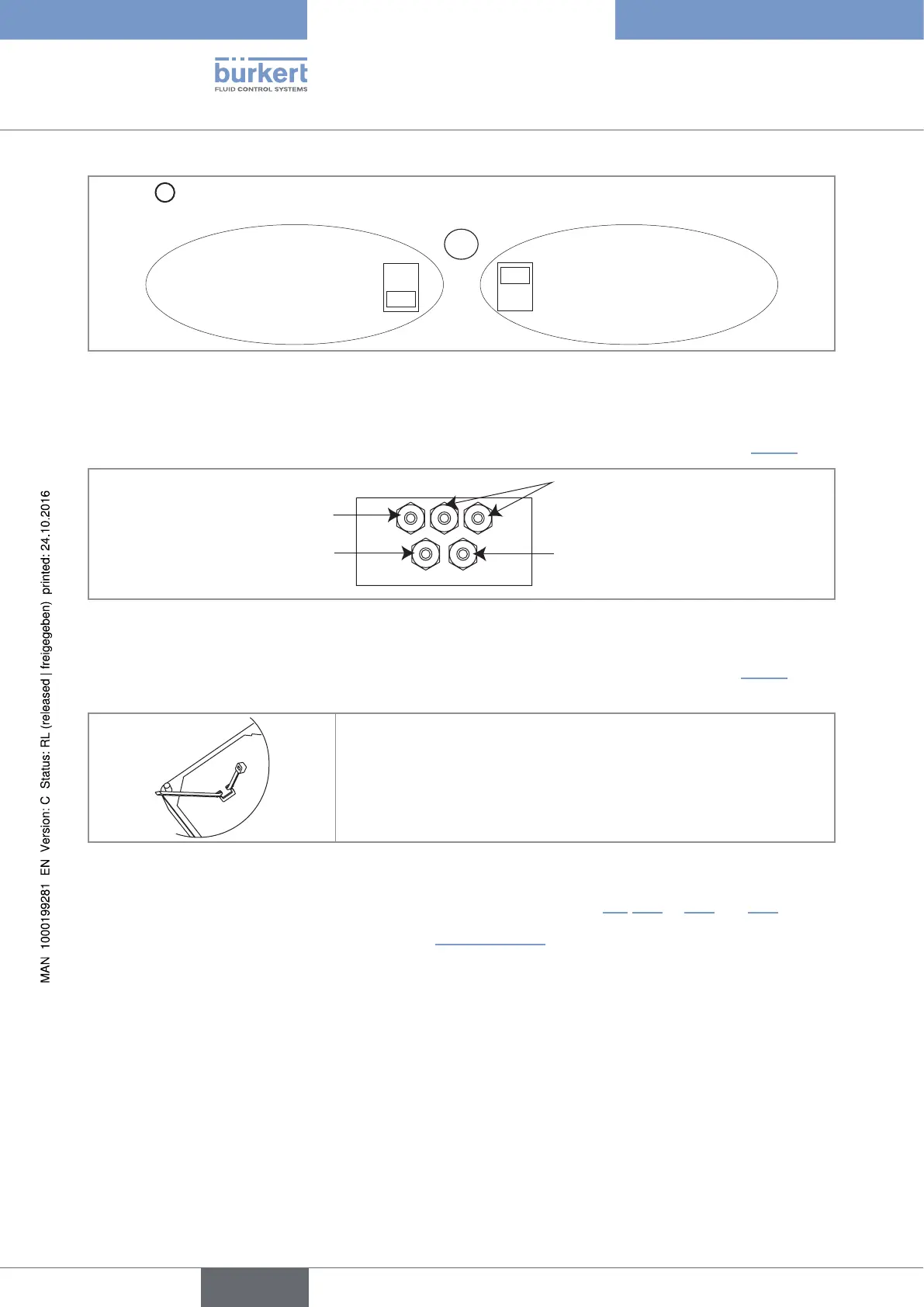
Selector
D
makes it possible to configure the supply voltage of the device in a 115/230 V AC version.
→ Energize the device with a
230 V AC voltage.
→ Energize the device with a
115 V AC voltage.
D
230V
115V
Fig. 30 : Selector of the supply voltage on a 115/230 V AC version
→ Loosen the nuts of the cable glands.
→ Insert each cable through a nut than through the cable gland, using the cable glands as shown in Fig. 31.
Cable of the flow sensor
Cables of the relay outputs DO2 and
DO3
Power supply cable
12...36 V DC or 115/230 V AC
Cable of the digital inputs and
the DO1 and DO4 outputs
Fig. 31 : Using the cable glands on a wall-mounted version
→ On a 115/230 V AC fed wall-mounted version, remove both terminal blocks (marked 7 and 8 in Fig. 25) from
the housing.
→ Before wiring the device insert the supplied cable clips into the slots of
the electronic board and of the 115/230 V AC power supply board if
the device has such a board.
Fig. 32 : Inserting the cable clips
→ Depending on the operating voltage of the device, wire according to chap. 8.9, 8.11 to 8.14 and 10.6.
→ Insert the two terminal blocks (marked 7 and 8 in Fig. 25, page 48) into their original position.
→ Letting the housing stay completely open, secure the power supply cable, the flow sensor connection cable
and the relay connection cables, with the cable clips.
→ Tighten the cable glands making sure the cable in the housing is long enough to allow complete opening of
the housing.
→ Close the cover.
→ Tighten the 4 screws.
→ Put the blanking strips on the housing.
English
Type 8025 - 8035 - SE35 BATCH