MV750i E, MV730i E, MV700i E, MV700 E, MV690 E
DISASSEMBLING
22
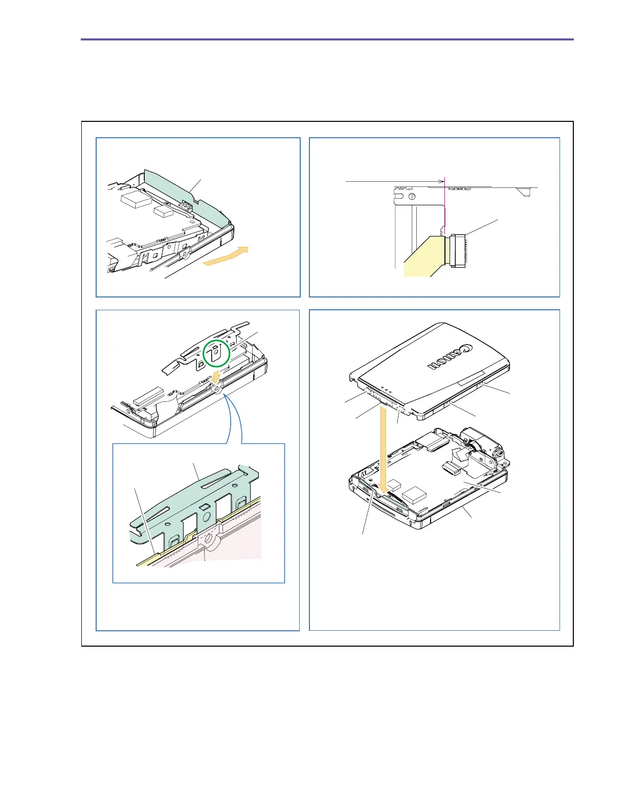
<Notes on Reassembling>
(1) Do not disfigure the LCD Bottom Cover Sheet.
(2) Mount the LCD Spring as illustrated.
(3) Insert a flexible cable into CN901 as illustrated.
(4) Mount the LCD Top Cover as illustrated.
Fig. 19
CN901
LCD Bottom Cover Sheet
E
LCD Spring
LCD Holder
LCD Bottom Cover
Claw A
Claw B
Claw C
Claw D
Rib
LCD Top Cover
LCD P.C.B.
LCD Bottom Cover
LCD Bottom Cover Sheet
Note on Reassembling (1)
Note on Reassembling (2)
Note on Reassembling (3)
Note on Reassembling (4)
Slide to introduce
Match the contour
Insert the rib of LCD Top Cover between LCD Bottom
Sheet and LCD P.C.B., and engage claws A to D in this
order. Tighten screws pressing the LCD Top Cover
against LCD Bottom Cover.
Insert the LCD Spring E between
LCD Bottom Cover and LCD Holder to mount.