MV750i E, MV730i E, MV700i E, MV700 E, MV690 E
DISASSEMBLING
23
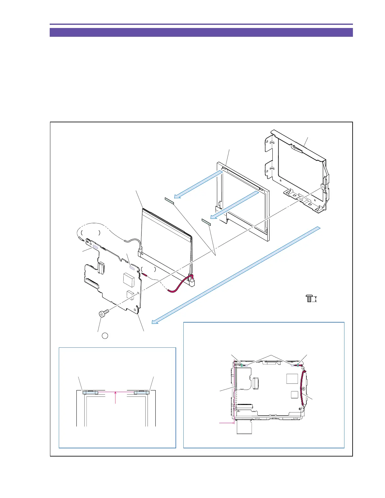
1-19 Disassembly of LCD Unit - 2
(1) Remove a screw (b × 1), separate two solder points (α) and, from the LCD Holder, detach the LCD P.C.B., Back Light Ass’y and
LCD Ass’y.
(2) Remove the LCD Sheet from the LCD Ass’y.
<Note on Reassembling>
(1) Attach the LCD Sheet at the illustrated position.
(2) Treat the Cable of LCD Back Light Ass’y as illustrated. After soldering, fasten the Cable with bond.
<Instruction for Supply>
LCD Back Light Ass’y : Dia Bond 1663G (CY9-8129-000)
Fig. 20
3mm
Metal
M1.7
b
(1)
(2)
(2)
LCD Holder
LCD Ass'y
Back Light Ass'y
White
(1) - α
(1) - α
Red
LCD P.C.B.
LCD Sheet
LCD SheetLCD Sheet
LCD Ass'y
Dia Bond Dia BondSolder
White Cable
Red Cable
Note on Reassembling (1)
Note on Reassembling (1), Instruction for Supply
Not beyond
this line
Attach upon pressing
against rib
(1) - b