SECTION 00 -- GENERAL INFORMATION -- CHAPTER 1
00-19
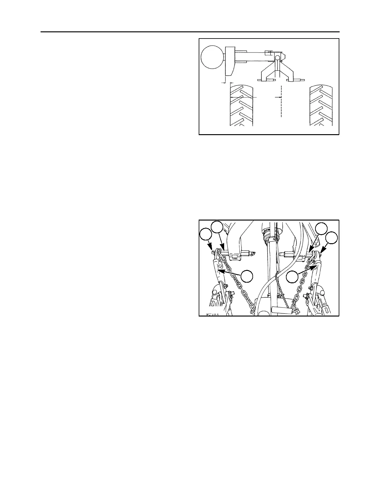
• For tractors that measure 1092 mm (43″),
position the hitch pins to the left so that only
the round pin protrudes on the right side of
the main frame arms. This will position the
mower towards the right, away from the right
side tractor tire.
NOTE: the tractor lower link arms may need to be
offset slightly to the right to prevent the mower PTO
shaft from contacting the inner end of the right hitch
pin.
• For tractors that measure more than 1092 mm
(43″), the tractor lower link arm sway bars or the
limit chains can be adjusted to further offset the
mower to the right, or the right side tire should be
moved inward.
IMPORTANT: The tractor lower links should be
placed straight behind the tractor, or the links location
should provide minimal offset. Excessive offset in
either direction may cause damage to the mower
PTO drive shaft due to excessive operating angles or
contact with hitch pins. The offset could also put
“lead” or “lag’ into the cutter bar, resulting in reduced
cutting width and proper breakaway performance.
1092 mm
(43″)
102 mm
(4″)
21
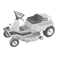
Attaching the mower to the tractor’s three-point
hitch
Attach the mower to the tractor’s three-point hitch as
follows:
1. Clean all paint and rust from the hitch pins, 1.
2. Attach the plate on the end of the limit chains to
the inner or outer end of the frame hitch pins, 1,
as required to clear obstructions on the tractor. If
installing on the outer end of the hitch pins, install
the limit chain plates before attaching the tractor
lower links.
3. Back the tractor to the mower and attach the
lower links, 2, to the outer end of the frame hitch
pins. Secure the links with linchpins, 3. Install the
linchpins from the top down.
NOTE: Attach the tractor lower links to the outside
pins only. Do not attach the lower links to the pins to
the inner side of the mower frame or damage to the
mower PTO drive shaft could occur.
600-1-1
1
1
2
2
3
3
22