SECTION 00 -- GENERAL INFORMATION -- CHAPTER 1
00-20
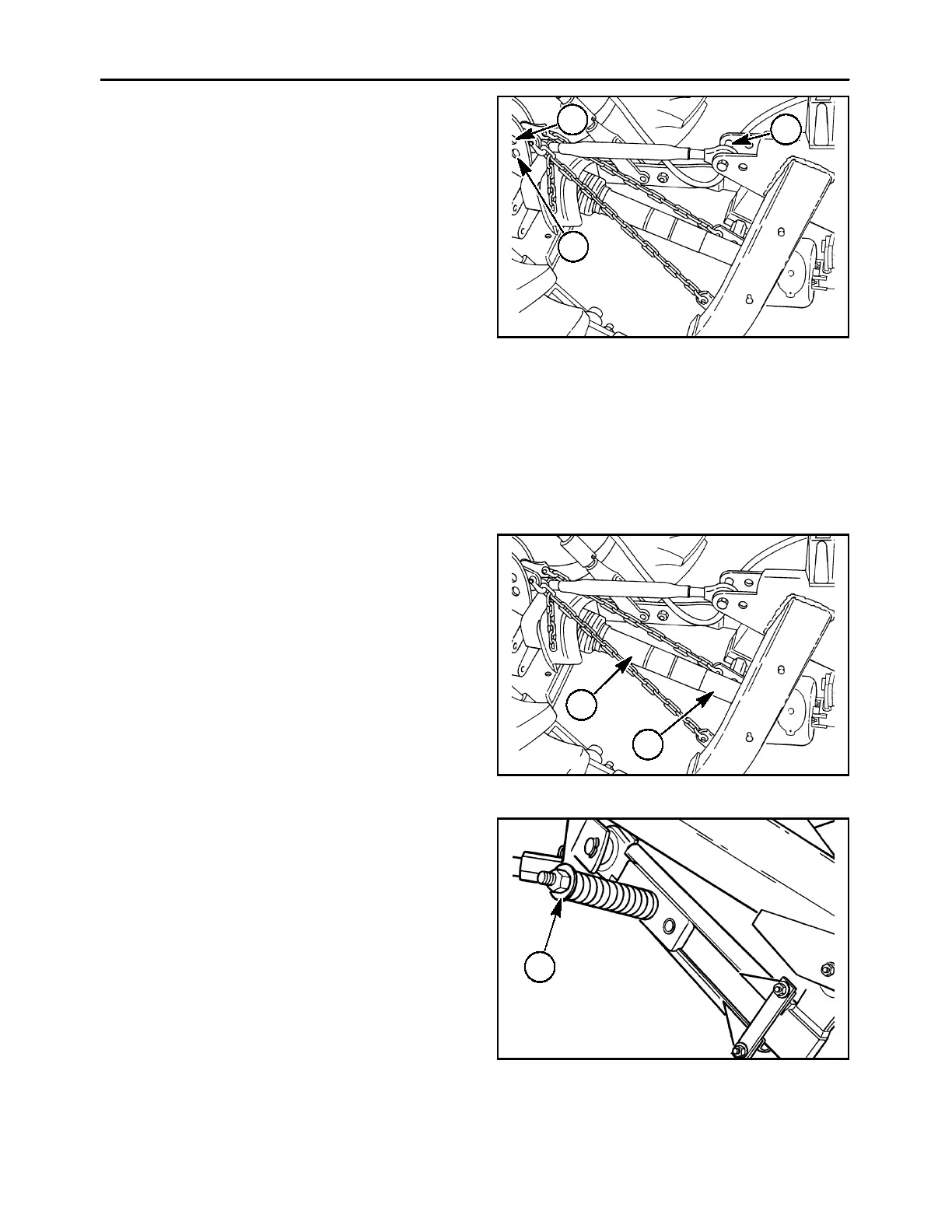
4. Attach the top link to the tractor, 1, using the pin
provided with the tractor top link.
5. Attach the top link to the mower, 2, in the front
hole using the pin provided with the mower.
NOTE: If necessary, the top link can be mounted in
the rear hole on the mower to allow greater top link
length range.
6. Attach the limit chain plates to the tractor at a top
link mounting position, 3, with the pin provided.
The limit chain length will be adjusted in following
steps for the minimum height of the hitch pins
above ground.
NOTE: If the limit chains interfere with or could
damage the tractor PTO shield, relocate the limit
chain plates to the opposite end of the mower frame
hitch pins or attach to a different location on the
tractor.
NOTE: It may be necessary to position the tractor
drawbar to the side or remove it to prevent
interference with the limit chains or PTO shaft.
A3680-13r
2
3
1
23
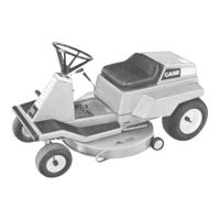
Attaching the PTO to the Tractor
The PTO assembly must be fitted to the tractor that
powers the mower. The PTO telescoping shield and
drive tubes must be long enough to overlap by at
least 102 mm (4″) while the mower and tractor
combination flex to a maximum distance from one
another. At the same time, the tubes, 1 and 2, must
be short enough so that they do not bottom out,
where the end of one tube contacts the base of the
other tube before the tubes are completely
collapsed.
NOTE: Some model tractors may require the PTO to
be shortened for proper operation. Refer to the
following pages for PTO adjustment.
A3680-13r
1
2
24
The assembly must have sufficient overlap so that
the tubes do not separate when the breakaway
system, 1, operates.
A3679-24
1
25