SECTION 58 -- ATTACHMENTS AND HEADERS -- CHAPTER 1
58-3
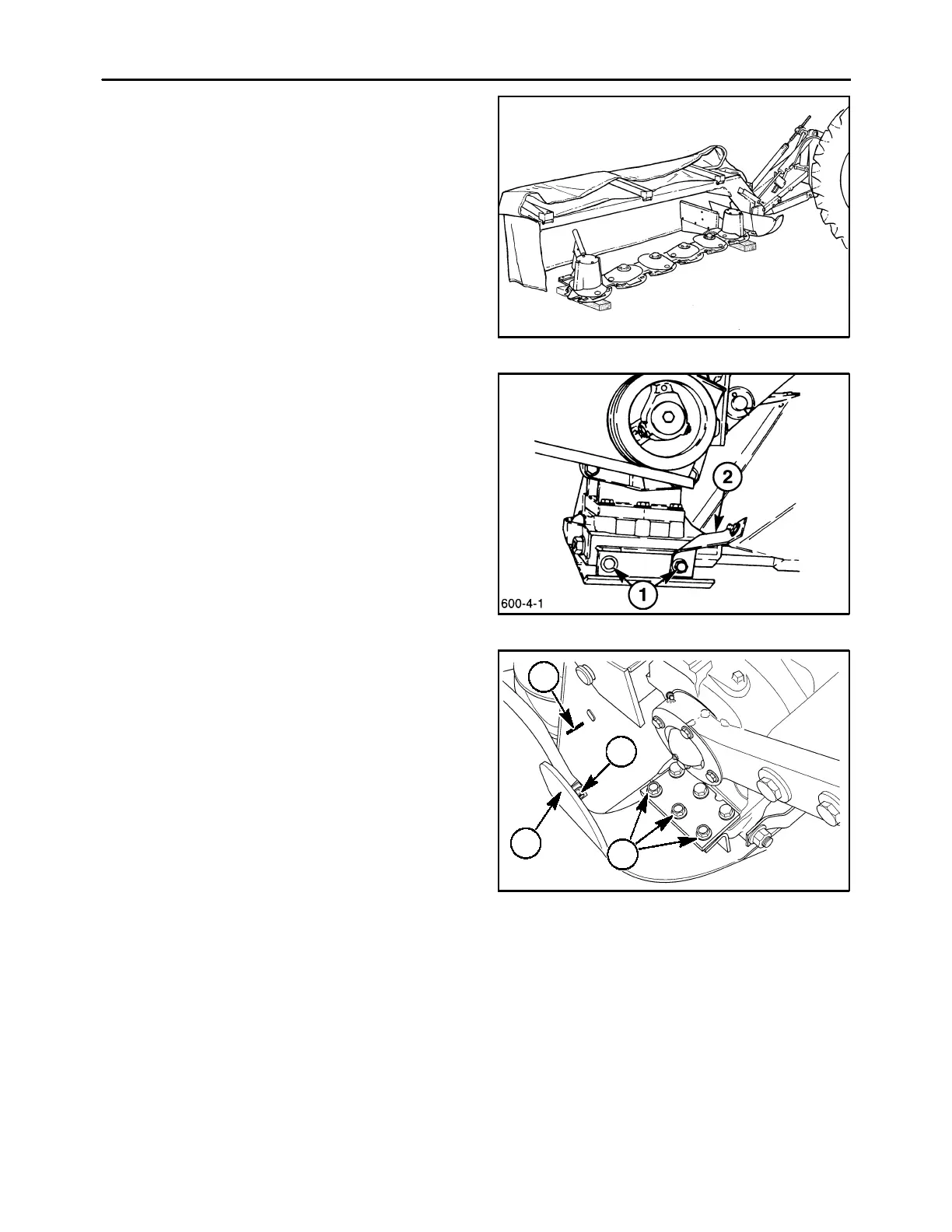
3. Lower the cutterbar onto blocks on a flat solid
surface so that the cutterbar is supported several
inches off the ground. The blocks should be
placed under the #1 disc module and the end disc
module.
A3680-20
3
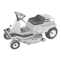
4. To remove the skid shoe from under the drive
module, first remove the two cap screws, 1, at the
rear of the skid shoe. Note that the right rear cap
screw also retains the inner shield mounting
bracket, 2.
4
5. Remove the three front cap screws, 1, that retain
the skid shoe and bevel gearbox to the drive
module, and the front bolt, 2, between the skid
shoe and the inner shield. Remove the skid shoe,
3, and the inner shield, 4, from unit.
Reinstall the three cap screws, 1, between the
bevel gearbox and the lower module. Raise the
unit and remove the blocking. Lower the unit onto
the floor.
NOTE: Reinstall the three cap screws, 1, before rais-
ing the mower to prevent failure of the bevel gearbox
and/or drive module.
19990604
1
4
2
3
5