11
Part to be welded
The part to be welded must always be connected to ground in order to reduce electromagnetic emission.
Much attention must be afforded so that the ground connection of the part to be welded does not increase the risk of accident to the user
or the risk of damage to other electric equipment.
When it is necessary to connect the part to be welded to ground, you should make a direct connection between the part and the ground
shaft.
In those countries in which such a connection is not allowed, connect the part to be welded to ground using suitable capacitors, in com-
pliance with the national regulations.
Welding parameters
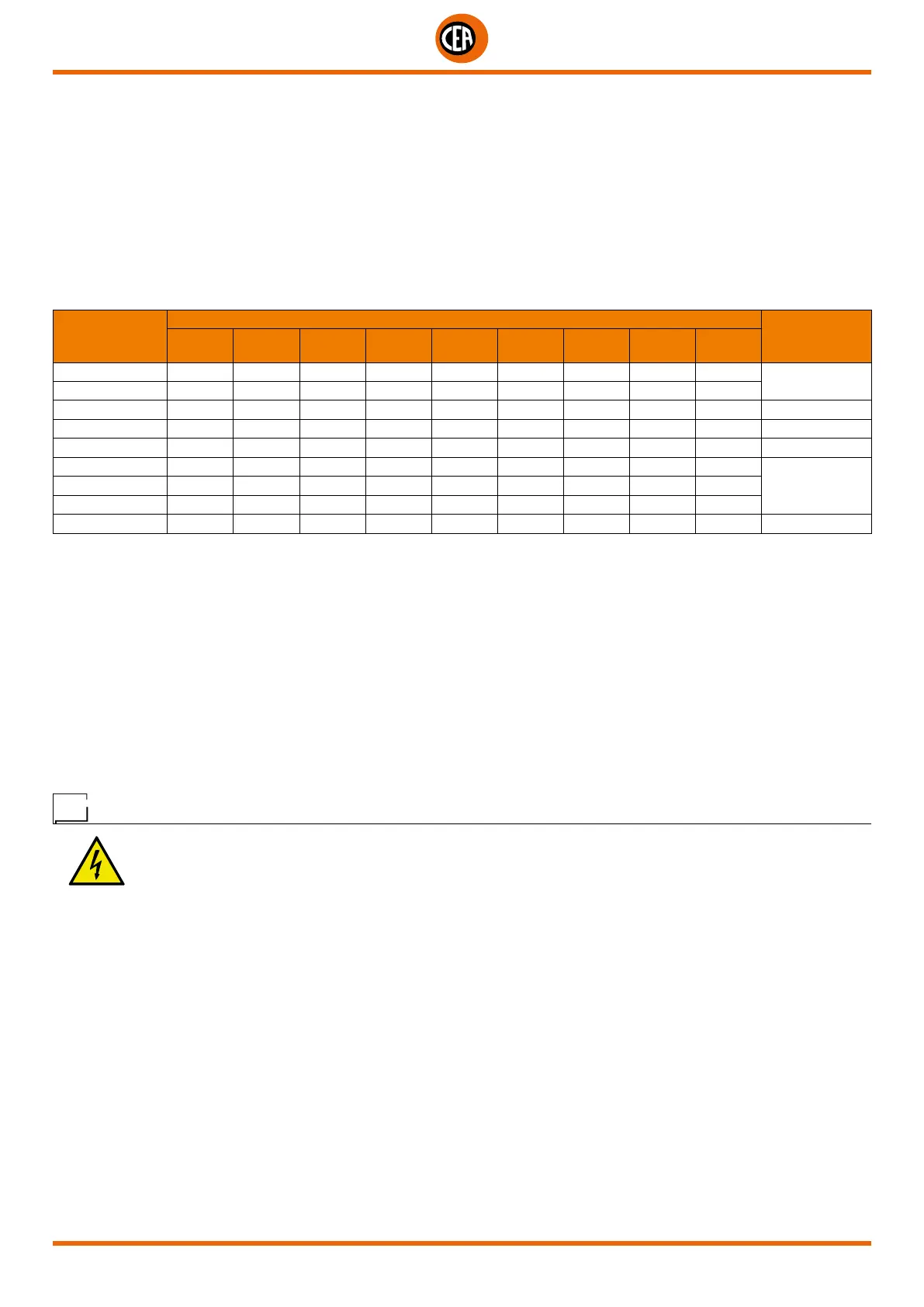
Table 4 shows the values of current to use with the respective electrodes for the welding of common steels and low-grade alloys. The-
se data have no absolute value and are indicative data only.
For a precise choice follow the instructions provided by the electrode manufacturer.
Table 4
Ø ELECTRODE
(mm)
ELECTRODE TYPE - Current adjustment field (A)
WELDING
THICKNESS
(mm)
6010
6011
6012 6013 6020 6027 7014
7015
7016
7018
7024
7028
1,6 - 20-40 20-40 - - - - - -
≤ 5
2 - 25-60 25-60 - - - - - -
2,4 40-80 35-85 45-90 - - 80-125 65-110 70-100 100-145 ≤ 6,5
3,2 75-125 80-140 80-130 100-150 125-185 110-160 100-150 115-165 140-190 > 3,5
4 110-170 110-190 105-180 130-190 160-240 150-210 140-200 150-220 180-250 > 6,5
4,8 140-215 140-240 150-230 175-250 210-300 200-275 180-255 200-275 230-305
> 9,55,6 170-250 200-320 310-300 225-310 250-350 260-340 240-320 260-340 275-365
6,4 210-320 250-400 250-350 275-375 300-420 330-415 300-390 315-400 335-430
8 275-425 300-500 320-430 340-450 375-475 390-500 375-475 375-470 400-525 > 13
The current to be used depends on the welding positions and the type of joint, and it increases according to the thickness and dimen-
sions of the part.
The current intensity to be used for the different types of welding, within the field of regulation shown in table 4 is:
• High for plane, frontal plane and vertical upwards welding.
• Medium for overhead welding.
• Low for vertical downwards welding and for joining small pre-heated pieces.
A fairly approximate indication of the average current to use in the welding of electrodes for ordinary steel is given by the following formula:
I = 50 × (Øe - 1)
Where:
I = intensity of the welding current
Øe = electrode diameter
Example:
For electrode diameter 4 mm
I = 50 × (4 - 1) = 50 × 3 = 150A
Maintenance
ATTENTION: Before carrying out any inspection of the inside of the generator, disconnect the system from the supply.
SPARE PARTS
Original spare parts have been specially designed for our equipment. The use of non-original spare parts may cause variations in per-
formance or reduce the foreseen level of safety.
We decline all responsibility for the use of non-original spare parts.
GENERATOR
As these systems are completely static, proceed as follow:
•
Periodic removal of accumulated dirt and dust from the inside of the generator, using compressed air. Do not aim the air jet directly
onto the electrical components, in order to avoid damaging them.
• Make periodical inspections in order to individuate worn cables or loose connections that are the cause of overheating.
 Loading...