4
• MMA
- Option to choose between the MMA DC and MMA AC electrode welding.
-
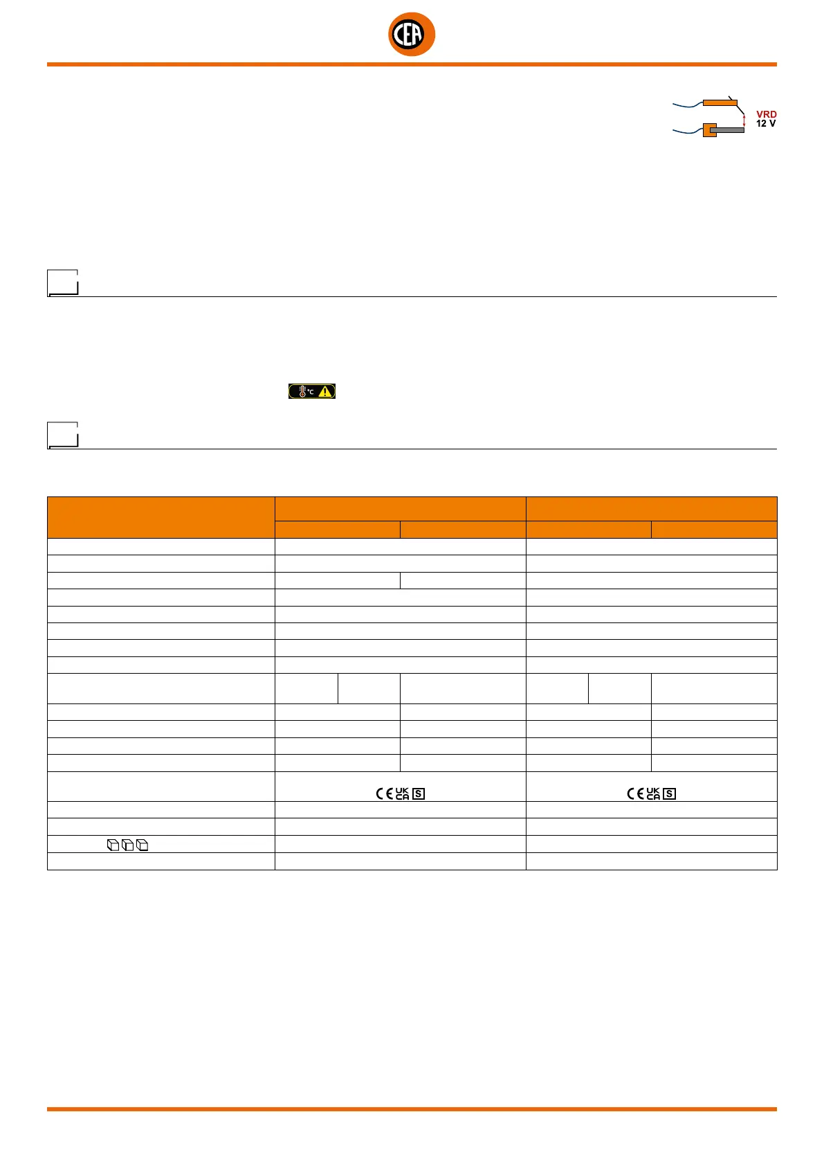
The VRD (Voltage Reduction Device) can be activated, which reduces voltages to below 12 V, which means
that the welding machine can be used in ambient conditions in which there is a high electrical risk, thereby
providing maximum operator safety.
- “Arc Force” adjustable to select the best dynamic characteristics for the welding arc.
- “Hot Start” adjustable to improve ignition with particularly difficult electrodes.
- Anti-sticking function to avoid the electrodes sticking.
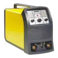
MATRIX X220 AC/DC
The PFC device makes the wave form of the current absorbed sinusoidal, which results in no harmonic disturbance on the mains and
optimisation of absorption, which allows you to use the generator’s full power with a 16 A fuse, as well as ensuring greater protection of
the welding machine against fluctuations in the power supply voltage.
Usage limits (IEC 60974-1)
The use of a welder is typically discontinuous, in that it is made up of effective work periods (welding) and rest periods (for the positio-
ning of parts, the replacement of wire and underflushing operations etc.
This welder is dimensioned to supply a I
2
max nominal current in complete safety for a period of work of X% of the total usage time. The
regulations in force establish the total usage time to be 10 minutes.
The work cycle is considered to be X% of this period of time. If the permitted work cycle time is exceeded, an overheat cut-off occurs to
protect the components around the welder from dangerous overheating.
Tripping of the trip switch is indicated by the
symbol on the display (see the manual for the XVision control panel).
After several minutes the overheat cut-off rearms automatically and the welder is ready for use again.
Technical data
The general technical data of the system are summarized in table 1.
Table 1
Model
MATRIX X220 AC/DC MATRIX X300 AC/DC
TIG MMA TIG MMA
Power supply 50/60 Hz V 1~ 230 ±20% 3~ 400 ±20%
Power supply: Z
max
Ω (*) 0,092
Input power @ I
2
Max kVA 6,5 7,0 9,6
Delayed fuse (I
2
@ 100%) A 16 10
Power factor / cosφ 0,99 / 0,99 0,95 / 0,99
Efficiency degree η 0,80 0,82
Input power at IDLE state W 20 15
Open circuit voltage V 85 85
Current range A
1÷220
(TIG DC)
3÷220
(TIG AC)
10÷180
1÷300
(TIG DC)
3÷300
(TIG AC)
10÷250
Duty cycle @ 100% (40°C) A 140 120 210 190
Duty cycle @ 60% (40°C) A 180 150 250 220
Duty cycle @ X% (40°C) A 220 (30%) 180 (30%) 300 (35%) 250 (40%)
Usable electrodes mm 1,2÷2,4 1,6÷4,0 1,2÷4,0 1,6÷5,0
Standards
IEC 60974-1 • IEC 60974-3 • IEC 60974-10
IEC 60974-1 • IEC 60974-3 • IEC 60974-10
Protection class IP 23 S IP 23 S
Insulation class F F
Dimensions
mm 530 - 410 - 215 530 - 410 - 215
Weight kg 19.8 21.4
IMPORTANT:
These systems, tested in accordance with the requirements of the EN/IEC 61000-3-3 standard, satisfy the requirements laid down by the EN/
IEC 61000-3-11 standard.
MATRIX X220 AC/DC
(*) This equipment meets the requirements laid down in the EN/IEC 61000-3-12 standard on harmonic currents.
MATRIX X300 AC/DC
This equipment complies with EN/IEC 61000-3-12 provided that the maximum permissible system impedance Z
max
is less than or equal to 0,092
at the interface point between the user’s supply and the public system. It is the responsibility of the installer or user of the equipment to ensure,
by consultation with the distribution network operator if necessary, that the equipment is connected only to a supply with maximum permissible
system impedance Z
max
less than or equal to 0,092.