9
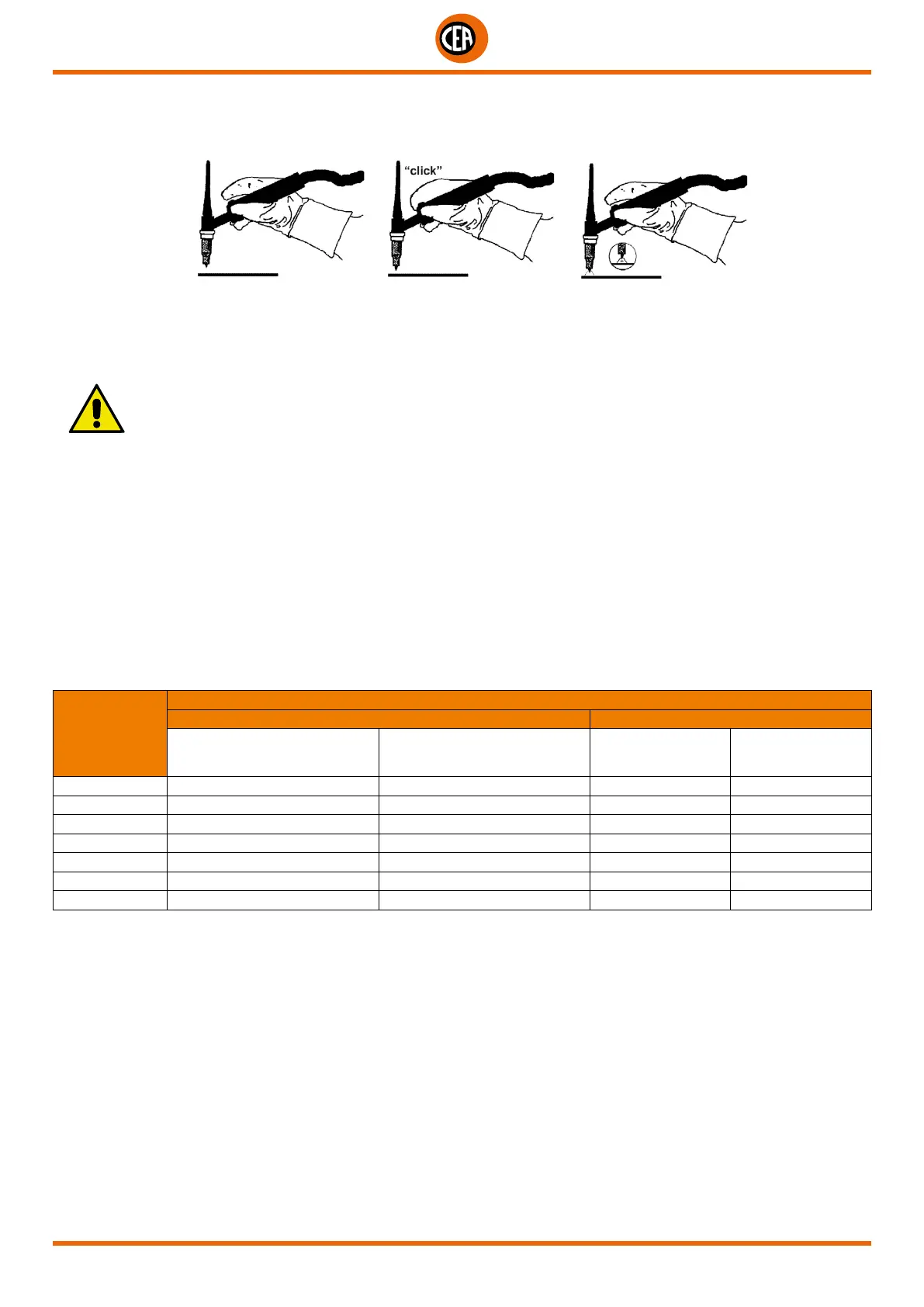
TIG welding with high frequency striking (HF)
4b) Open the gas cylinder and flow regulator.
5b) Put the electrode at the point at which welding is to begin, put the TIG torch at an angle so that the edge of the gas nozzle is not on
top of the piece to be welded, keeping a 2-3 mm gap between the point of the electrode and the piece to be welded (Fig. E-1).
2000HA72
1 2 3
Fig. E
6b) Press the torch button.
7b) The voltaic arc strikes even without contact between the TIG torch electrode and the workpiece (Fig. E-2).
8b) To continue welding put the torch back in its normal position (Fig. E-3).
IMPORTANT: The high frequency switches off automatically after switching on.
Part to be welded
The part to be welded must always be connected to ground in order to reduce electromagnetic emission.
Much attention must be afforded so that the ground connection of the part to be welded does not increase the risk of accident to the user
or the risk of damage to other electric equipment.
When it is necessary to connect the part to be welded to ground, you should make a direct connection between the part and the ground
shaft.
In those countries in which such a connection is not allowed, connect the part to be welded to ground using suitable capacitors, in com-
pliance with the national regulations.
Welding parameters
Table 3 shows the currents to use with the respective electrodes for TIG welding. This input is not absolute but is for your guidance only;
read the electrode manufacturers’ instructions for a specific choice. The diameter of the electrode to use is directly proportional to the
current being used for welding.
Table 3
Ø ELECTRODE
(mm)
ELECTRODE TYPE - Current adjustment field (A)
TIG DC TIG AC
Tungsten
Ce 1%
Grey
Tungsten
Rare ground 2%
Turchoise
Tungsten
Pure
Green
Tungsten
Rare ground 2%
Turchoise
1 10-50 10-50 - -
1,6 50-80 50-80 30-60 30-60
2,4 80-150 80-150 60-120 60-120
3,2 150-250 150-250 80-160 80-160
4 200-400 200-400 100-240 100-240
4,8 - - 200-300 200-300
6,4 - - 275-400 275-400