Chapter 3 – Installation & Wiring
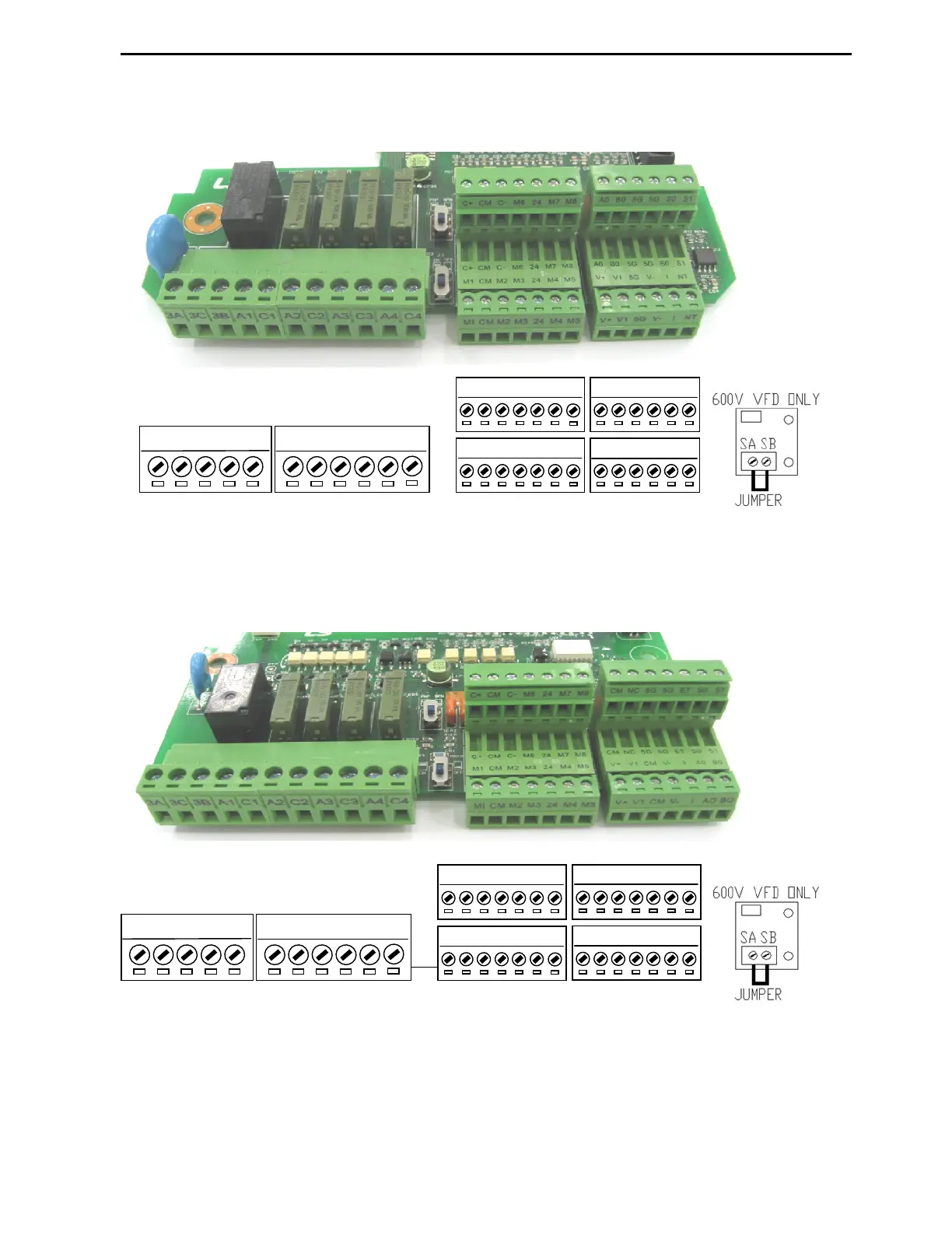
3.2.4 Digital and Analog control circuits terminals layout
7.5~40HP (5.5 ~ 30kW) 200V/400V/600V Class VFDs
All CM terminals are connected together and all 5G terminals are connected together internally.
50~700HP (37~525kW) 400V and 50~150HP (37~110kW) 600V Class VFDs
Note: All CM terminals are connected together and all 5G terminals are connected together internally.
A0
B0
5G
5G
S0
S1
V+
V1
5G
V-
I
NT
C+
CM
C-
M6
24
M7
M8
M1
CM
M2
M3
24
M4
M5
3A
3C
3B
A1
C1
A2
C2
A3
C3
A4
C4
C+
CM
C-
M6
24
M7
M8
M1
CM
M2
M3
24
M4
M5
3A
3C
3B
A1
C1
A2
C2
A3
C3
A4
C4
CM
NC
5G
5G
ET
S0
S1
V+
V1
CM
V-
I
A0
B0