Chapter 3 – Installation & Wiring
3.2.6 Power Wiring
Wiring Recommendations
1) Do not connect input power to VFD Motor terminals U, V, and W otherwise VFD can be damaged.
2) Do not run input power and motor wires in the same conduit, otherwise the VFD can malfunction or be
damaged.
3) Do not run input power wires or motor leads for multiple VFDs in common conduit.
4) Do not install power factor correction capacitors, surge suppressors, or RFI filters on the VFD output.
These devices can trigger some VFD faults or even damage the VFD.
5) Use ring type terminals for the VFD power wiring.
6) Do not leave wire fragments, metal shavings or other metal objects inside the VFD, otherwise VFD can
be damaged.
7) Size power wire to maintain a voltage drop less than 2% at VFD or motor terminals.
8) Install a line reactor for VFDs in pump systems with dedicated service transformer to protect VFD from
transient power surges and provide some degree of harmonics distortion mitigation.
9) Install an output reactor to protect motor winding if distance from 460V VFD to the motor is greater
than 45 feet and less than 100 feet. Install an output filter if distance from 460V VFD to the motor is
greater than 100 feet or application is a submersible pump motor . Install an output filter if distance from
230V VFD to the motor is greater than 200 feet.
10) Always check if DC bus charge LED is OFF and DC voltage on the terminals P1+ and N- is less
than 30VDC before working on VFD wiring. The DC bus capacitors may hold high-voltage charge for
several minutes after the VFD power is disconnected.
Grounding
1) Connect a dedicated ground wire from power transformer or power distribution panel to VFD ground
terminal and dedicated ground wire from VFD to the motor for ground fault protection proper operation.
If metal construction or conduits are used as a ground leak current path, the VFD can have inadequate
grounding and ground fault protection.
2) Ground VFD to the power source ground and motor ground to avoid electrical shock. The ground
impedance for 230VAC VFDs should be less than 100 and 10 for 460VAC and 600VAC VFDs.
3) Connect ground wire first before any other wires. Connect only to the dedicated ground terminal of the
VFD. Do not use the case or the chassis assembly screws for grounding.
4) VFD Grounding wire should be as short as possible.
5) Do not install a ground rod at VFD package if it is not a service entrance rated panel, otherwise the VFD
can intermittently trip on Ground Fault.
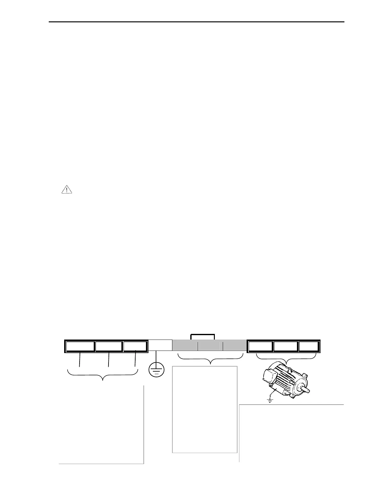
Power and Motor Connections for 7.5~40HP (5.5~30kW) VFDs
R(L1) S(L2) T(L3)
G P1(+) P2(+) N(-) U V W
L1 L2 L3
be connected to the R, S, and
T terminals and single-phase
power to R and S terminals.
The proper phase sequence is
not necessary.
Do not apply power to
motor terminals U, V, and
W, otherwise the VFD can
Three-phase motor must be
connected to the U, V, and W
terminals. If VFD starts in forward
direction, the motor shaft should
rotate clockwise when viewed from
motor to the load. If rotation is not
correct, swap any two motor leads.
Do not remove P1+
and P2+ jumper
and do not connect
any wires to VFD
terminals P1+, P2+
and N- except
dynamic braking unit
, otherwise the VFD
can be damaged.
Ground