Chapter 6 - Parameter Description
6-27
Parameter
Code
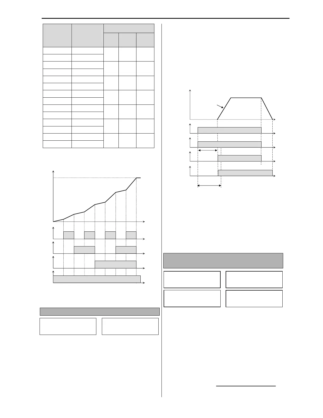
Accel/Decel
Time #
XCEL
H
(M3)
M
(M2)
L
(M1)
I/O-50 Accel Time-1
0 0 1
I/O-51 Decel Time-1
I/O-52 Accel Time-2
0 1 0
I/O-53 Decel Time-2
I/O-54 Accel Time-3
0 1 1
I/O-55 Decel Time-3
I/O-56 Accel Time-4
1 0 0
I/O-57 Decel Time-4
I/O-58 Accel Time-5
1 0 1
I/O-59 Decel Time-5
I/O-60 Accel Time-6
1 1 0
I/O-61 Decel Time-6
I/O-62 Accel Time-7
1 1 1
I/O-63 Decel Time-7
[Multi-Accel/Decel Time Operation]
$)04605+"'8" !G"
I/O-68 has three selections: None, Damper and
Lubrication.
None- Damper/Lubrication mode is disabled.
Damper- Damper mode is enabled. If AUX relay is
set to Damper in I/O-76~79 and start signal is
received, the AUX relay contact will be closed to
activate a damper actuator and after time delay, set
in I/O-69, the VFD will start the motor. If any
digital input is set to Damper Switch in I/O-20~27,
the VFD will start the motor only when tDamper
Switch closes. If it is not activated during I/O-69
Damper Timer, the VFD will trip on Damper Fault.
Thus, the Damper Timer should be set longer than
it normally takes for the damper to open. The
damper AUX relay and timer will be activated at
every VFD start.
Lubrication- The lubrication mode for hollow
shaft pumps is enabled. If any AUX relay is set to
Lubrication in I/O-76~79 and start signal is
received, the AUX relay contact will be closed for
I/O-69 Lube Timer in order to activate a lubrication
solenoid valve. When Lube timer expires, a
lubrication solenoid will be deactivated and VFD
will start the motor.
$)3*A3.+%!-*! -' '
!!
I/O-70, 72 Analog 0-10VDC outputs have five
selections: Frequency, Current, Voltage, kW and
External PID Out. I/O-71 and I/O-73 are parameters
for analog outputs scaling factors.
[Frequency]
S0 or S1 output provides 0-10VDC signal
corresponding to VFD speed output from 0Hz to
Max. frequency. The output voltage is determined
by scaling factor set in I/O-71 and I/O-73.
P
QRRSRTU
QRRSRTUQRRSRTU
QRRSRTU
P
[Out.Freq.] x [I/O-71] x 10V
[Max.Freq] x 100
M1
ON
Output Frequency
Time
Time
ON
Time
ON
Time
ON
Time
ON
ON
ON
ON
Freq.
I/O
S0 Mode
70 Frequency
I/O
S0 Adjust
71 100 %
I/O
S1 Mode
72 Current
I/O
S1
Adjust
73 100 %
Damper
Relay
VFD Run
Command
ON
Output Frequency
Time
ON
ON
ON
Damper
Timer
Damper
Actuator
VFD
Acceleration
VFD Run
Output
I/O
Dmpr LubeSel
68 None
I/O
Dmpr/LubeTMR
69 30 sec