CAUTION: No attempt should be made to support or
lift either engine application using the intake mani-
fold, or any other location on engine not specified
below.
3.3 LTR ENGINE
(1) Mount Fixture, Engine Support Special Tool
7137 or equivalent across engine compartment (Fig. 5).
Using nylon webbing material such as seat belt mate-
rial or equivalent, mount it to the following locations
on the 3.3 ltr. engine.
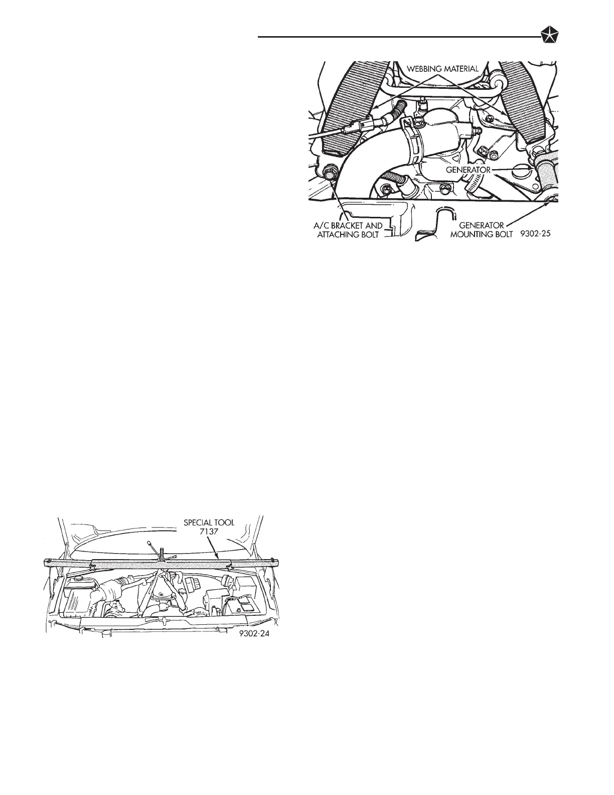
(2) Remove bolt attachingA/C compressor bracket to
front of engine. Install webbing material hook on A/C
compressor bolt, install bolt and tighten (Fig. 5 and 6).
(3) Loosen but do not remove generator to engine
mounting bolt, remove spacer between generator and
engine. Install webbing material hook between genera-
tor and engine, re-install and tighten original bolt (Fig.
5 and 6).
(4) Remove electronic ignition coil, mounting
bracket bolt from rear of engine. Install webbing
material hook on bracket bolt and re-install and
tighten bolt. Note: Route webbing material be-
tween fuel injector rail and valve cover, not
between fuel injector rail and intake manifold.
(5) Mount remaining piece of webbing material to
left cylinder head using threaded hole on back of
cylinder head. Using a bolt of the correct thread size
and length, install webbing hook on bolt. Then install
bolt into threaded hole on back of cylinder head and
tighten bolt.
(6) Securely attach pieces of webbing material to
hook on engine holding fixture (Fig. 5). Tightenhook on
engine holding fixture until all slack is remove from all
4 pieces of webbing material.
3.5 LTR ENGINE
(1) Mount Fixture, Engine Support Special Tool
7137 or equivalent across engine compartment (Fig. 7).
Using nylon webbing material such as seat belt mate-
rial or equivalent, mount it to the following locations
on the 3.5 ltr. engine.
(2) Remove bolt attaching timing belt housing to
front of engine assembly (Fig. 7 and 8). Install web-
bing material hook on timing belt housing attaching
bolt, install bolt and tighten (Fig. 7 and 8).
(3) Remove generator to generator mounting
bracket attaching nut and bolt (Fig. 9). Install web-
bing material hook on generator mounting bolt, re-
install and tighten original nut and bolt (Fig. 9).
(4) Mount remaining pieces of webbing material to
back of right and left cylinder head using the
threaded hole on back of cylinder heads. Using a bolt
of the correct thread size and length, install webbing
hook on bolt. Then install bolt into threaded hole on
back of cylinder heads and tighten bolt.
(5) Securely attach pieces of webbing material to
hook on engine holding fixture (Fig. 7). Tighten hook
on engine holding fixture until all slack is remove
from all 4 pieces of webbing material.
CRADLE ASSEMBLY REMOVAL ALL ENGINES
(1) Raise vehicle on jackstands or centered on a
frame contact type hoist. See Hoisting in the Lubri-
cation and Maintenance section of this manual, for
the required lifting procedure to be used for this ve-
hicle.
(2) Remove both front wheel and tire assemblies
from the vehicle.
(3) Remove left and right ball joint stud to steering
knuckle clamp nut and bolt (Fig. 10).
CAUTION: When lower control is separated from
steering knuckle, do not let ball joint seal hit up
against steering knuckle. If ball joint seal hits steer-
ing knuckle, seal damage may occur. If ball joint
seal becomes torn, replace seal before assembling
lower control arm to knuckle.
Fig. 6 Front Engine Support Attaching Locations 3.3 Ltr.
Fig. 5 Engine Supporting Fixture Installed 3.3 Ltr.
2 - 24 SUSPENSION AND DRIVESHAFTS
 Loading...