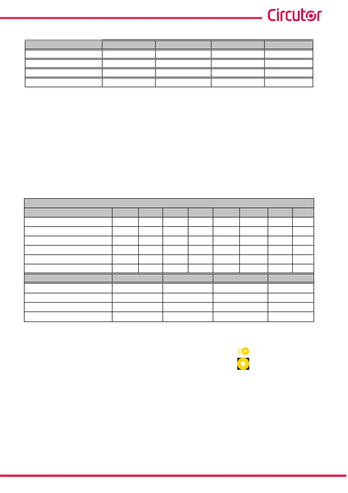
Table 32 (Continuation): Code of variables for programming the digital outputs and transistor�
Variable Module 1
(23)
Module 2
(23)
Module 3
(23)
Module 4
(23)
Analogue input I1 934 942 950 958
Analogue input I2 935 943 951 959
Analogue input I3 936 944 952 960
Analogue input I4 937 945 953 961
(21)
In the CVM-A1x00-FLEX version, the neutral current is a calculated parameter, except in Single-Phase connec-
tion mode, where it is not supported.
(22)
The integrated variables are those that the device has as standard.
(23)
If in the device there is more than one module connected with the same type of inputs, the module with the
lowest number is the one with the lowest serial number.
(24)
When programming as an alarm a digital input programmed as logic state if:
- You program the maximum value = minimum value = 0 the output will show an alarm when the input has
a value of 1.
- You program the maximum value = minimum value = 1 the output will show an alarm when the input has
a value of 0.
Any other combination of values will cause erroneous behaviour of the alarm.
The pre-alarm value is not considered.
(25)
Codes valid only for programming the digital outputs of the transistor in impulse mode.
(26)
Codes not valid for programming analogue outputs.
Table 33: Code of the quality variables used for programming the digital and transistor outputs�
Quality variables
(27)
Variable Phase Code Phase Code Phase Code Phase Code
PST Flicker (Pst) L1 97 L2 98 L3 99 - -
K-factor L1 100 L2 101 L3 102 - -
Voltage peak factor L1 103 L2 104 L3 105 - -
Current peak factor L1 106 L2 107 L3 108 - -
Quality event L1 109 L2 110 L2 111 III 112
Transient L1 113 L2 114 L3 115 III 116
Variable Code
% V Unbalance (Kd) 64 - - -
% I Unbalance (Kd) 66 - - -
% V Asymmetry(Ka) 65 - - -
% I Asymmetry(ka) 67 - - -
(
27)
The quality variables cannot be congured in the expansion modules.
● When programming the pre-alarm value:
If the device exceeds the programmed pre-alarm value, the icon is activated on the
display, and the icon that indicates the alarm status changes colour: .
The value is programmed in %.
● When programming the minimum value below which the relay is activated:
The units and maximum and minimum values of the variables to program are shown in
Table 34.
● When programming the maximum value above which the relay is activated:
The units and maximum and minimum values of the variables to program are shown in
Table 34.
203
Instruction Manual
CVM-A1000 - CVM-A1500