7�- EXPANSION MODULES
The device has following expansion modules that can be connected to it.
The modules are:
Transistor Digital Inputs/Outputs (M-CVM-AB-8I-8OTR),
Relay Digital Inputs/Outputs (M-CVM-AB-8I-8OR)
Analogue Inputs/Outputs (M-CVM-AB-4AI-8AO)
Modbus TCP Bridge communications module (M-CVM-AB-Modbus-TCP(Bridge))
LonWorks communications module (M-CVM-AB-LON)
Probus communications module (M-CVM-AB-Probus)
MBus communications module (M-CVM-AB-MBus)
Modbus TCP Switch communications module (M-CVM-AB-Modbus-TCP(Switch))
The device accepts a maximum of 3 expansion modules.
Depending on the modules connected, total consumption will not exceed 15W.
The device only accepts one communications module of each type.
7.1.- INSTALLATION
Before installing the expansion module the device must be unplugged from all
power supplies, both the device's and the measurement system's internal power
supply.
If more than one expansion module is installed, they must be ordered by
serial number, i�e�, the module with the lowest serial number must be the
rst installed in the device.
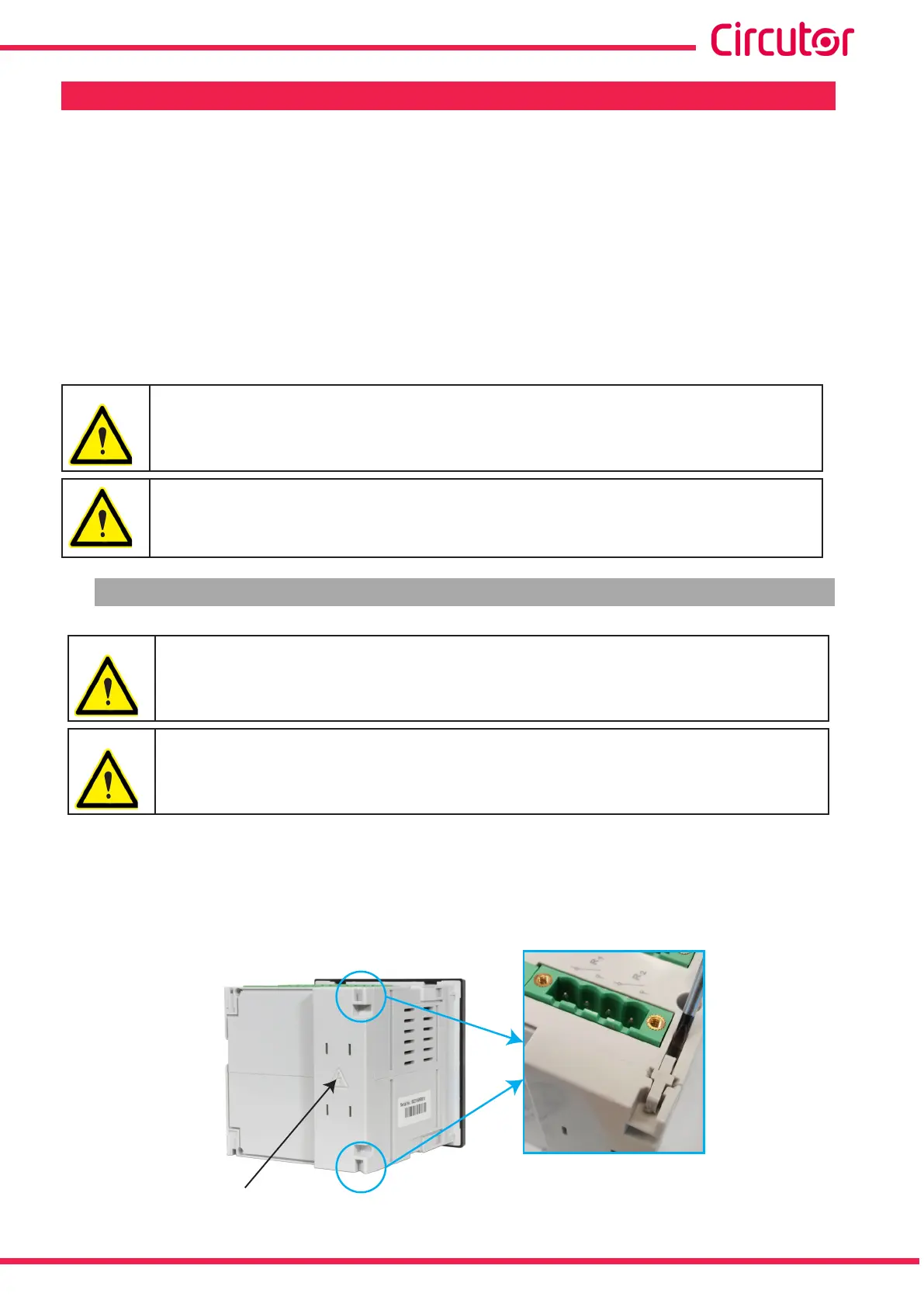
To install, rstly remove the protective cover of the expansion connector located at the rear of
the device. To do so:
A�- Remove the two fastening pins that secure the protective cover with a at tip screwdriver,
Figure 326.
Protective cover
Figure 326: Remove the two fastening pins�
263
Instruction Manual
CVM-A1000 - CVM-A1500