(77)
When programming the Programming status manually set the output for the relays manually, using the Value
parameter. The conguration of the relay digital outputs programmed in the device no longer works.
The relays work in automatic mode according to the conguration programmed in the device.
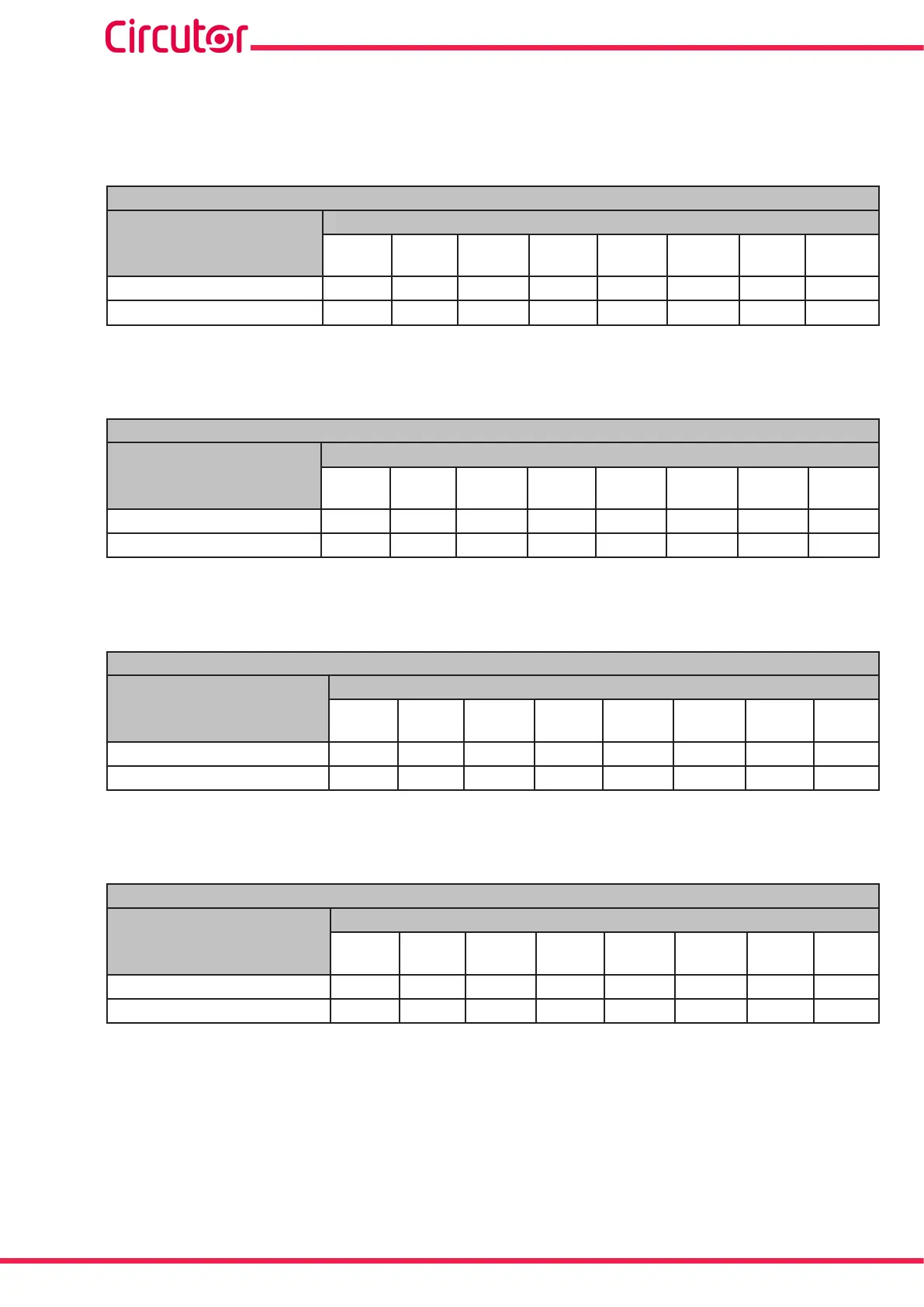
Table 94: Modbus memory map: Manual programming of outputs, expansion modules (Table 2)�
Manual programming of relay digital outputs: Slot 1
Configuration variable
Address
Output
1
Output
2
Output
3
Output
4
Output
5
Output
6
Output
7
Output
8
Programming status C428
C43C C450 C464 C478 C48C C4A0 C4B4
Value
C429
C43D C451 C465 C479 C48D C4A1 C4B5
Note: The 2 registers must be written at once (as a group), otherwise it will respond with an
error.
Table 95: Modbus memory map: Manual programming of outputs, expansion modules (Table 3)�
Manual programming of relay digital outputs: Slot 2
Configuration variable
Address
Output
1
Output
2
Output
3
Output
4
Output
5
Output
6
Output
7
Output
8
Programming status C810
C824 C838 C84C C874 C874 C888 C89C
Value
C811
C825 C839 C84D C875 C875 C889 C89D
Note: The 2 registers must be written at once (as a group), otherwise it will respond with an
error.
Table 96: Modbus memory map: Manual programming of outputs, expansion modules (Table 4)�
Manual programming of relay digital outputs: Slot 3
Configuration variable
Address
Output
1
Output
2
Output
3
Output
4
Output
5
Output
6
Output
7
Output
8
Programming status CBF8
CC0C CC20 CC34 CC48 CC5C CC70 CC84
Value
CBF9
CC0d CC21 CC35 CC49 CC5D CC71 CC85
Note: The 2 registers must be written at once (as a group), otherwise it will respond with an
error.
Table 97: Modbus memory map: Manual programming of outputs, expansion modules (Table 5)�
Manual programming of relay digital outputs: Slot 4
Configuration variable
Address
Output
1
Output
2
Output
3
Output
4
Output
5
Output
6
Output
7
Output
8
Programming status CFE0
CFF4 D008 D01C D030 D044 D058 D06C
Value
CFE1
CFF5 D009 D01D D031 D045 D059 D06D
Note: The 2 registers must be written at once (as a group), otherwise it will respond with an
error.
274
CVM-A1000 - CVM-A1500
Instruction Manual