8-10
Cisco ASR 1000 Series Aggregation Services Routers Hardware Installation Guide
OL-13208-11
Chapter 8 Cisco ASR 1002 Router Overview and Installation
Cisco ASR 1002 Router Description
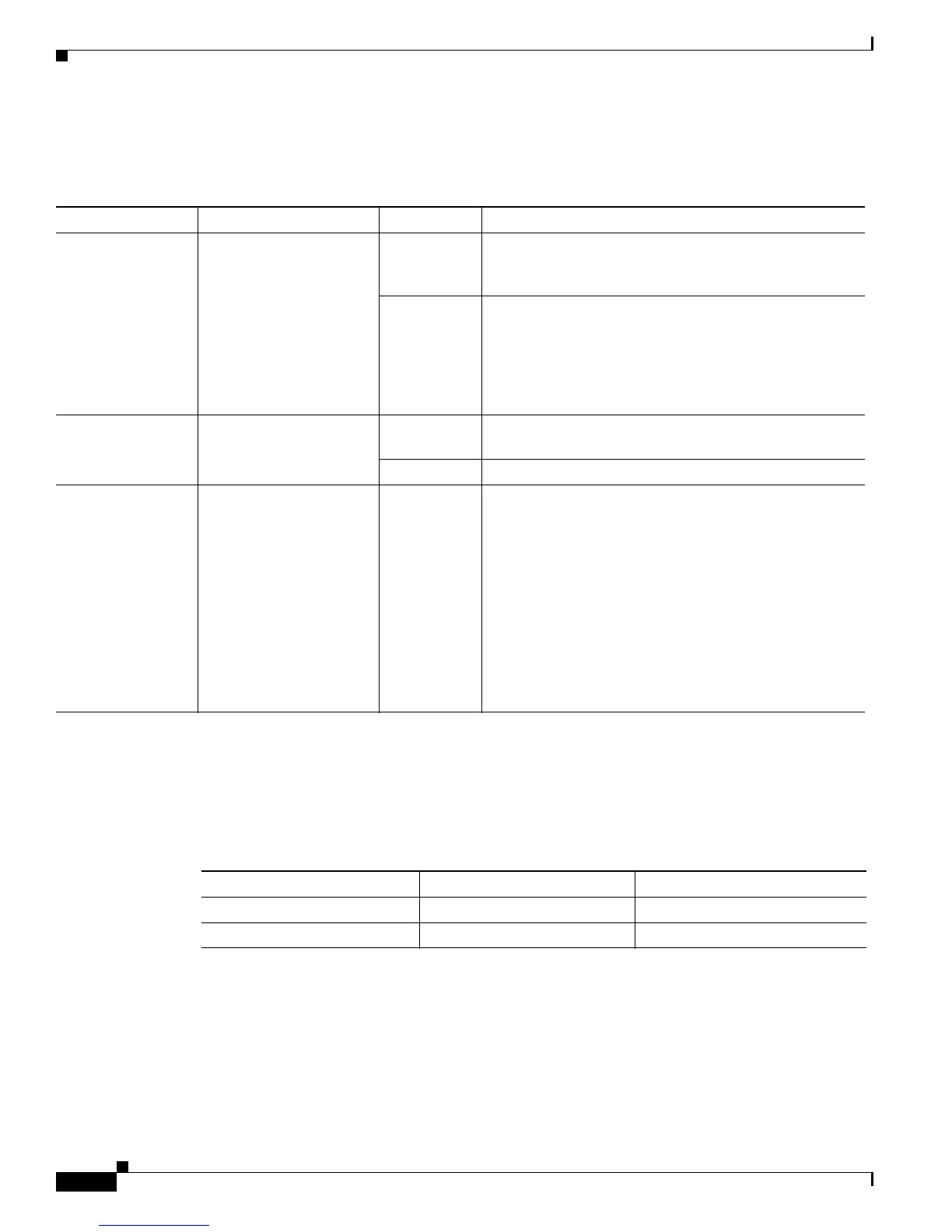
The Cisco ASR 1002 Router –48 VDC power supply LEDs are described in Table 8-3.
Table 8-3 Cisco ASR 1002 Router –48 VDC Power Supply LEDs
The output voltage alarm is declared when the output voltage is below the low end of the minimum or
above the high end of the maximum limits. When the output voltage is above the high end of the
minimum or below the low end of the maximum limits, the red state will not be activated.
Table 8-4 shows the –48 VDC power supply output voltage alarm range.
+24 VDC Power Supply for Cisco ASR 1002 Router
This section provides information about the +24 VDC power supplies on the rear of the Cisco ASR 1002
Router. The recommended branch circuit breaker for the Cisco ASR 1002 Router +24 VDC power
supply is a 40 A UL listed circuit breaker.
LED Label LED Color Description
INPUT OK A bi-color LED indicates
presence of input voltage
Green LED illuminates green to signal that the DC power supply
input voltage is greater than 43.5VDC at turn-on and
remains green down to 39VDC.
Amber The LED illuminates amber if the power supply turns off
due to low input voltage (falls below 39VDC) and
indicates that there is still a hazard present (voltage on the
terminal block). The LED remains amber and is active to
around 20 V +/-5 V. The LED is not illuminated if the
input is below 15 V.
FAN OK A bi-color LED indicates
power supply fan status
Green The LED illuminates s green when all fans are
operational.
Red The LED illuminates red when a fan failure is detected.
OUTPUT FAIL Power supply activity Red When the LED is off, it signals that the DC output voltage
are within the normal operating range. Output voltage
between the minimum and maximum limits will not
create an output fail alarm, and output voltages below the
minimum or above the maximum will create an Output
Fail alarm.
Led illuminates red to indicate that the DC output is out
of the specified range.
When you turn the power supply on, the red LED
illuminates for two to three seconds to test LED operation
before going off.
Table 8-4 –48 VDC Power Supply Output Voltage Alarm Threshold Ranges
Output Minimum Maximum
12V 10.0-11.2V 12.8-13.8V
3.3V 2.6 - 3.0 V None

 Loading...


