10-41
Cisco ASR 1000 Series Aggregation Services Routers Hardware Installation Guide
OL-13208-11
Chapter 10 Cisco ASR 1002-X Router Overview and Installation
Cisco ASR 1002-X Router Power Supplies
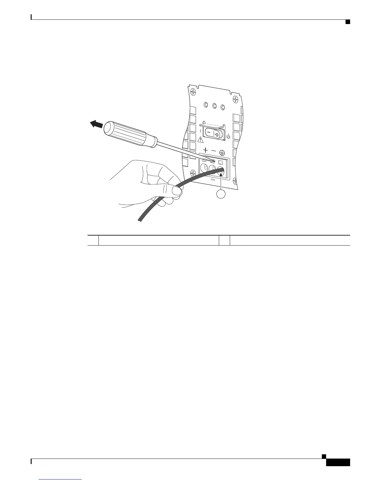
Figure 10-30 shows a lead wire that is fully inserted, and the screwdriver being removed while you
gently tug the lead wire.
Figure 10-30 Removing a Screwdriver from the +24 VDC Power Supply Terminal Block
Step 8
Repeat Steps 5 through Step 10 for each lead wire.
1 Gently tug the lead wire. — —
OUT
PUT I
NPUT
F
A
I
L
OK
O
K
F
A
N
T
his unit m
ight hav
e
more than
o
ne pow
er supply con
n
e
c
tion.
All connections m
ust
be
r
em
ov
ed
to de-energize the unit.
+27V DC INPUT
+2
7V
32A
1
253169

 Loading...


