10-44
Cisco ASR 1000 Series Aggregation Services Routers Hardware Installation Guide
OL-13208-11
Chapter 10 Cisco ASR 1002-X Router Overview and Installation
Connecting External Cables to the Cisco ASR 1002-X Router
Note Each Cisco ASR 1000 Series Route Processor 1 must have a console port connection (typically to a
terminal server) if you are running a redundant configuration in the chassis.
Perform the following procedure to connect a terminal to a console port:
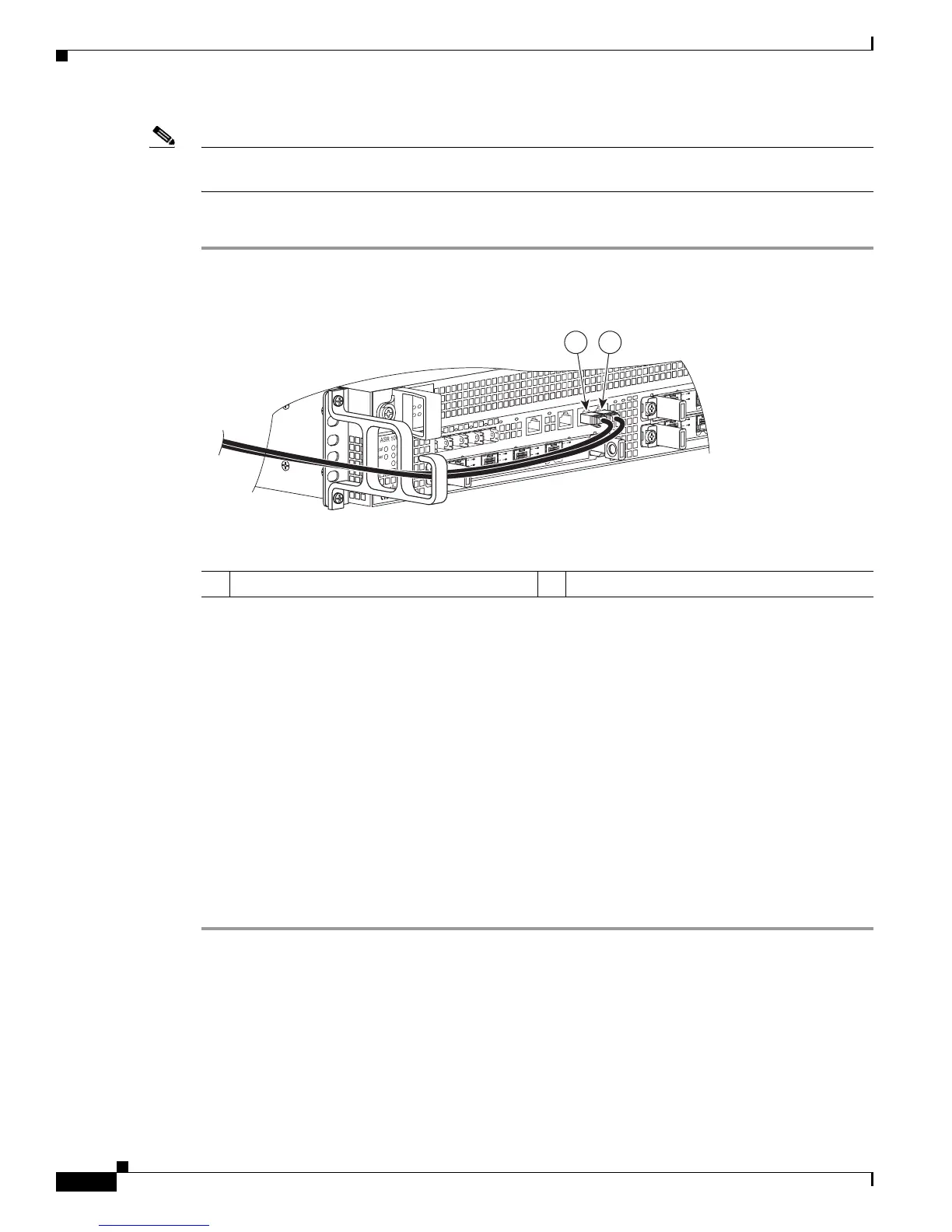
Step 1 Connect one end of the RJ-45 cable to the serial RJ-45 port (CON) on the front panel (see Figure 10-33).
Figure 10-33 Cisco ASR 1002-X Router Console Port Connection on the Route Processor
Step 2
Run the cable up and through the cable management bracket and connect the other end of the RJ-45 cable
to the RJ-45 adapter (see Figure 10-33).
Step 3 Connect the adapter to your video terminal to complete the cable connection.
Step 4 Power on your video terminal.
Step 5 Configure your video terminal to match the following default console port settings:
• 9600 baud
• 8 data bits
• No parity generation or checking
• 1 stop bit
• No flow control
Step 6 Continue with the installation by referring to the procedure described in the “Connecting External
Cables to the Cisco ASR 1002-X Router” section on page 10-44.
Connecting External Cables to the Cisco ASR 1002-X Router
Keep the following guidelines in mind when connecting external cables to the Cisco ASR 1002-X
Router:
• To reduce the chance of interference, avoid crossing high-power lines with any interface cables.
1 CON port connection 2 AUX port connection
280285
ASR 1002
stat
pwr
min
maj
crit
0
1
C
/
A
A
/
L
0
1
C/
A
A/
L
S
TAT
Q
E0
Q
E
1
QE
2
Q
E3
B
OOT
CA
R
RI
E
RLI
N
K
P
WR ST
A
TM
T
S
M
GMT
AU
X
CO
N
S
P
A
-
4X
O
C
3-
P
O
S
S
T
AT
U
S
0
1
2
3
C
/
A
A
/
L
C
/
A
A
/
L
C/A
A
/
L
C
/
A
A
/
L
1 2
 Loading...


