11-32
Cisco ASR 1000 Series Aggregation Services Routers Hardware Installation Guide
OL-13208-11
Chapter 11 Cisco ASR 1013 Router Overview and Installation
Connecting Power to the Cisco ASR 1013 Router
Note DC input power cables must be connected to the PDU terminal studs in the proper positive
(+) and negative (–) polarity. In some cases, the DC cable leads are labeled, which is a
relatively safe indication of the polarity. However, you must verify the polarity by measuring
the voltage between the DC cable leads. When making the measurement, the positive (+)
lead and the negative (–) lead must always match the (+) and (–) labels on the power
distribution unit.
• A ground cable is required for each DC PDU. We recommend that you use at least 6-AWG
multistrand copper wire. This wire is not available from Cisco Systems; it is available from any
commercial cable vendor.
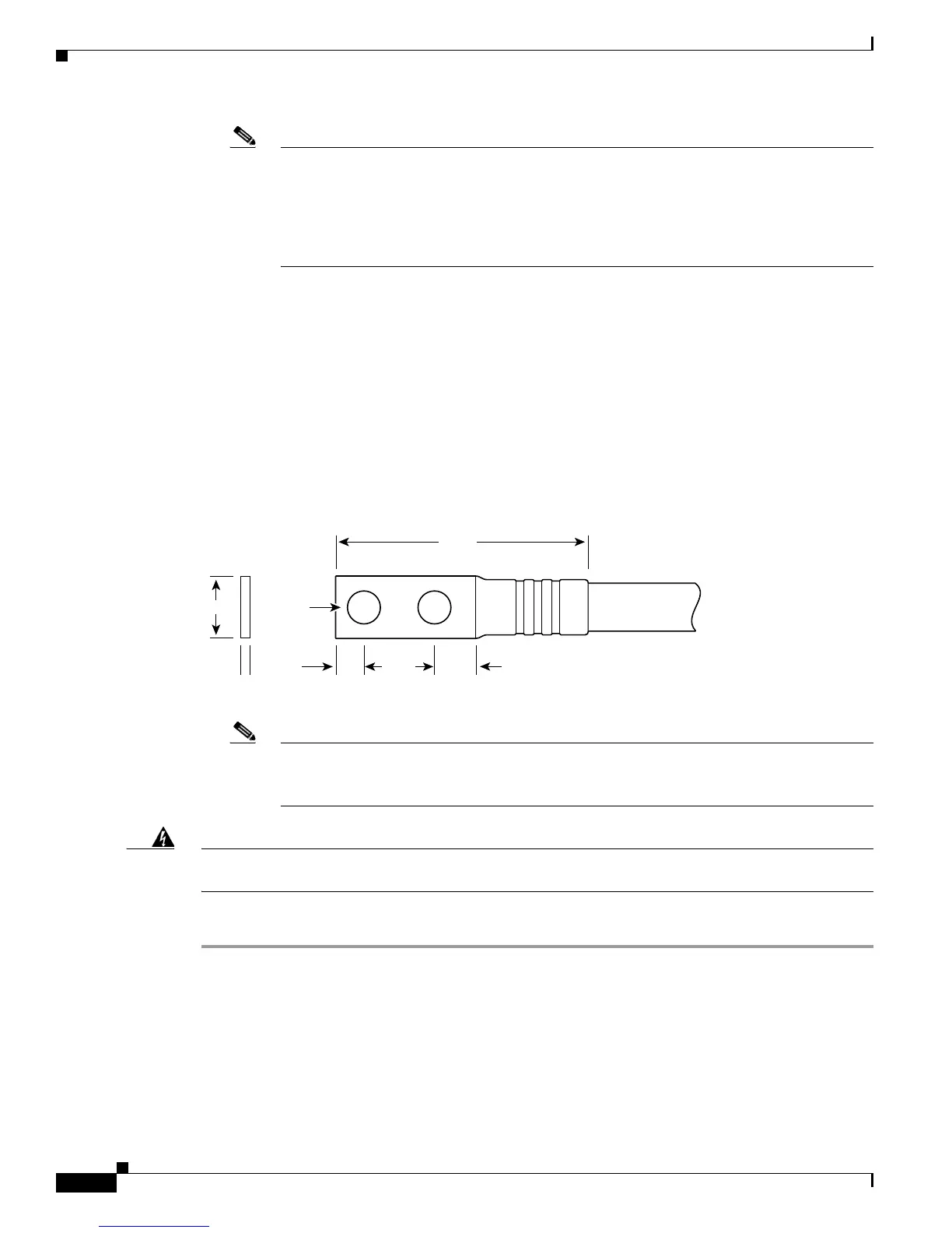
The ground wire cable lug should be dual-hole (as shown in Figure 11-15) and able to fit over M6
terminal studs at 0.625 inch (15.88mm) centers. Recommended lug terminal wire size Panduit part
number:
–
LCD8-14A-L for 8AWG wire size
–
LCD6-14A-L for 6AWG wire size
Figure 11-15 DC Input Power Cable Lug
Note To avoid hazardous conditions, all components in the area where DC input power is
accessible must be properly insulated. Therefore, before installing the DC cable lugs, be sure
to insulate the lugs according to the manufacturer’s instructions.
Warning
When you install the unit, the ground connection must always be made first and disconnected last.
Statement 1046
To connect the DC power supply, follow these steps:
Step 1 Make certain that the chassis grounding is connected before you begin installing the DC power supply
Step 2 Locate the stud (see Figure 11-16, callout 6) on the DC power supply for the GND connection which
must be connected first and follow these steps:
a. Using the grounding lug, replace the washers and Kepnut screw in the following order.
–
Flat washer
–
Grounding cable lug
Crimp area
25527
2.24
0.48
0.08
0.25 0.370.63
End View
Ø 0.267
2 holes
All measurements in inches
 Loading...


