11-34
Cisco ASR 1000 Series Aggregation Services Routers Hardware Installation Guide
OL-13208-11
Chapter 11 Cisco ASR 1013 Router Overview and Installation
Connecting Power to the Cisco ASR 1013 Router
Step 5 You must wrap the positive and negative lead cables with sleeving. Take each lead wire and cover the
area from the lug to the wire with heavy shrink sleeving (see Figure 11-17).
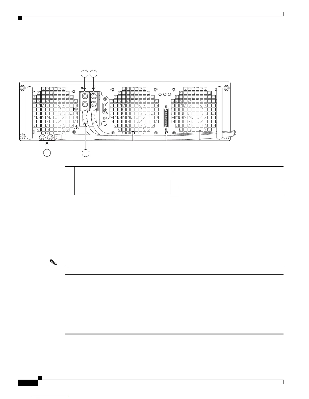
Figure 11-17 DC Power Supply Terminal Block Ground Cable Lugs
Step 6
For easier cable-management, insert the negative lead cable first. Replace the ground lug with cable in
the following order:
a. Flat Washer
b. Ground lug with negative wire
c. Kepnut screw
Step 7 Tighten the Kepnut screw to recommended torque of 18 in-lbs minimum to 22 in-lbs maximum for the
positive stud and wire.
Note Secure the wires coming in from the terminal block so that they cannot be disturbed by casual contact.
Step 8 Use tie wraps to secure the wires, so that the wires are not pulled from the terminal block by casual
contact. Ti-wrap studs are located below the power supply terminal block (see Figure 11-18).
Step 9 Replace the terminal block plastic cover and tighten the screw. The plastic cover is slotted and keyed to
fit correctly over the terminal block.
Step 10 Remove the tape from the circuit-breaker switch handle and move the circuit-breaker handle to the
on position.
Step 11 Switch the circuit breaker switch to the On (|) position.
This completes the procedure for connecting the DC power supply in the Cisco ASR 1013 Router.
1 Negative lug and wire with sleeving
wrapped around the wire and end of lug
3 Location of sleeving wrapped around the wire
and end of the grounding stud
2 Positive lug and wire with sleeving wrapped
around the wire and end of lug
4 Ground lug and wire
OUTPUT INPUT FAN
FAIL OK OK
ALARMS
60V
1A MAX
This unit might have more than one power supply connection. All connections must be removed to de-energize the unit.
-48/-60V 40A
253913
1 2
4
3
 Loading...


