14-60
Cisco ASR 1000 Series Aggregation Services Routers Hardware Installation Guide
OL-13208-11
Chapter 14 Removing and Replacing FRUs from the Cisco ASR 1000 Series Routers
Removing and Replacing the Cisco ASR 1006 Router Power Supplies
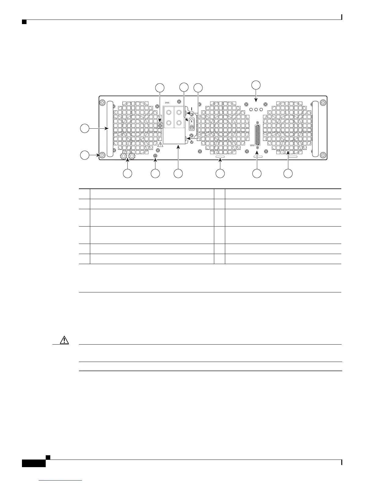
Figure 14-41 shows the ASR1013/06-PWR-DC power supply and components.
Figure 14-41 Cisco ASR 1006 Router DC Power Supply (ASR1013/06-PWR-DC)
Removing the DC Power Supply from Cisco ASR 1006 Router
Before you can remove a DC power supply from the Cisco ASR 1006 Router, you must remove power
from the power supply. Follow these steps to remove power and the DC power supply from the chassis.
Caution Make certain that the chassis ground is connected before you begin removing and installing the power
supply. For the chassis ground stud location.
Step 1 Before servicing the power supply, switch the circuit breaker Off in your equipment area. As an
additional precaution, tape the circuit breaker switch in the Off position.
Step 2 Slip on the ESD-preventive wrist strap that was included in the accessory kit.
Step 3 Switch the power supply circuit breaker switch to Off (O).
Step 4 Locate the terminal block on the rear of the chassis on the power supply.
1 Fan 7 DC power supply captive screw
2 DB-25 alarm connector* 8 DC power supply handle
3 Tie-wrap tab 9 Terminal block and plastic cover single
screw
4 DC power supply terminal block and plastic
cover
10 On/Off (|/O) circuit breaker switch
5 Ground symbol 11 Terminal block and plastic cover slot tab
6 DC power supply ground studs 12 Power supply LEDs
*For information about the DB-25 alarm connector, how it works, and Cisco ASR 1000 route processor LEDs, see the “How
Cisco ASR1000-RP Alarm Monitoring Works” section on page 2-20.
Note: Shielded cables must be used to connect to the DB-25 alarm connector on both the AC and DC power supplies, in order
to comply with FCC/EN55022/CISPR22 Class A emissions requirements.
253912
OUTPUT INPUT FAN
FAIL OK OK
ALARMS
60V
1A MAX
This unit might have more than one power supply connection. All connections must be removed to de-energize the unit.
-48/-60V 40A
2 145 36
7
8
12
9
10
11
 Loading...


