A-17
Cisco ASR 1000 Series Aggregation Services Routers Hardware Installation Guide
OL-13208-11
Appendix A Cisco ASR 1000 Series Router Specifications
Cisco ASR 1001 Router Specifications
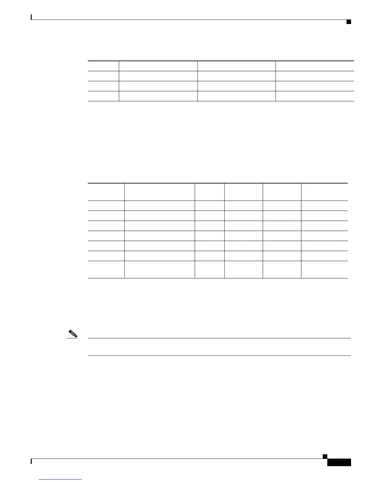
Cisco ASR 1013 Router DB-25 Pinout Assignments for Alarm Relays
Table A-30 lists the common, normally open, and normally closed relay contacts accessible to an
external alarm monitoring facility by means of the DB-25 connector.
For more information about the DB-25 alarm connector, see Cisco ASR 1006 Router DB-25 Pinout
Assignments for Alarm Relays, page A-4.
Cisco ASR 1001 Router Specifications
This section lists the specifications for the Cisco ASR 1001 Router. Table A-31 lists the Cisco ASR 1001
Router physical specifications.
Note The Cisco ASR 1001 Router has the route processor, embedded services processor, and SIP integrated
in the chassis.
5 TX Ring Unused —
6TX TIP Unused —
7,8 N/C — —
Table A-29 BITS RJ-45 Interface Pinouts (continued)for Cisco ASR 1013 Router (continued)
Pin Signal Direction Description
Table A-30 Cisco ASR 1013 Router DB-25 Alarm Connector Pinout Assignments
Signal Description
Common
(CM)
Normally
Open (NO)
Normally
Closed (NC) SPARE
CRTAA Critical Audible Alarm 2 1 14 —
MAJAA
Major Audible Alarm
16 3 15 —
MINAA
Minor Audible Alarm
54 17 —
CRTVA
Critical Visual Alarm
19 6 18 —
MAJVA
Major Visual Alarm
87 20 —
MINVA
Minor Visual Alarm
22 9 21 —
SPARE SPARE—unused pin
reserved for future use
— — — 10, 11, 12, 13,
23, 24, 25

 Loading...


