B-4
Cisco ASR 1000 Series Aggregation Services Routers Hardware Installation Guide
OL-13208-11
Appendix B Cisco ASR 1000 Series Router Route Processor and Embedded Services Processor Signals and Pinouts
Cisco ASR1000-ESP40 Console Port Pinout Specifications
Console Port Signals and Pinouts
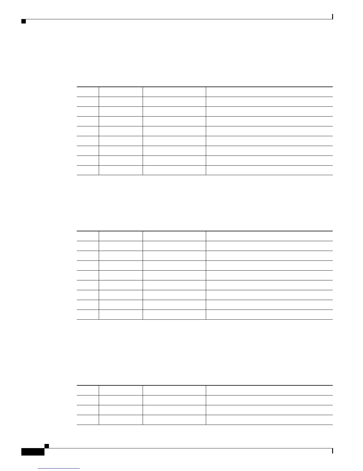
Table B-7 lists the pinouts of the dual RJ-45 ports for the front panel console port.
Auxiliary Port Signals and Pinouts
Table B-8 lists the pinouts of the dual RJ-45 ports for the auxiliary port signals.
Cisco ASR1000-ESP40 Console Port Pinout Specifications
Cisco ASR1000-ESP40 provides a debug console on a 10-pin header. Table B-9 lists the console port
pinouts for Cisco ASR1000-ESP40.
Table B-7 Console Port Pinouts
Pin Signal Direction Description
1 RTS Output Request to Send (tied to pin 8, CTS)
2 DTR Output Data Terminal Ready (always On)
3 TXD Output Transmit Data
4 RI Input Ring Indicator
5GND — —
6 RXD Input Receive Data
7 DSR/DCD Input Data Setl Ready/Data Carrier detect
8 CTS Input Clear to Send
Table B-8 Auxiliary Port Pinouts
Pin Signal Direction Description
1 RTS Out Request to Send
2 DTR Out Data Terminal Ready (Always On)
3 TXD Out Transmit Data
4 RI — Ring Indicator
5GND — —
6 RXD In Receive Data
7 DSR/DCD In Data Set Ready/Data Carrier Detect
8 CTS In Clear to Send
Table B-9 Console Port Pinout for Cisco ASR1000-ESP40
Pin Signal Direction Description
1— — Not Connected
2 DSR In Unused
3 RXD In Receive Data
 Loading...


