2-28
Cisco ASR 1000 Series Aggregation Services Routers Hardware Installation Guide
OL-13208-11
Chapter 2 Cisco ASR 1000 Series Routers Component Overview
Power Supplies for the Cisco ASR 1006 Router
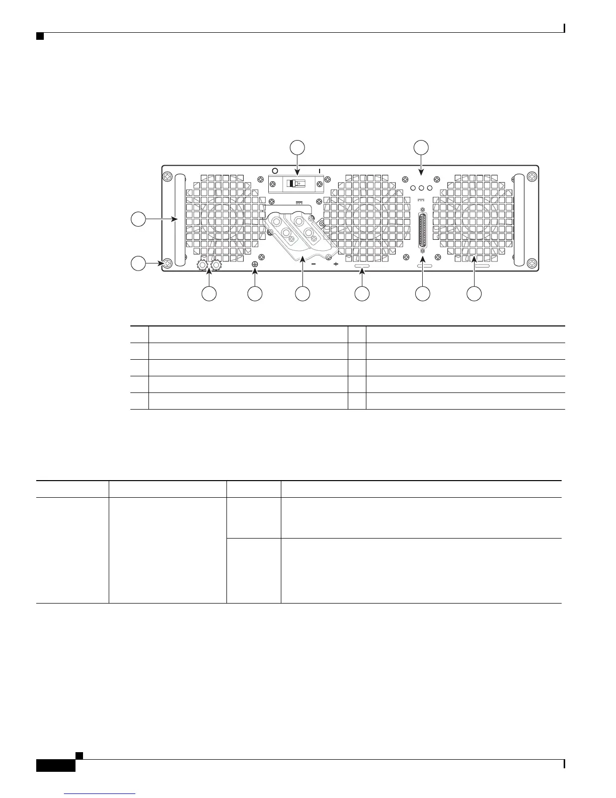
Figure 2-7 shows the –48 VDC power supplies at the rear of the Cisco ASR 1006 Router. The Cisco ASR
1006 Router supports up to two power supplies.
Figure 2-7 Cisco ASR 1006 Router –48 VDC Power Supply
Table 2-14 describes the power supply LEDs and connectors on the rear of the chassis.
1 Fans 6 Ground lugs
2 DB-25 alarm connector 7 Captive screws
3 Tie-wrap tabs 8 Power supply handle
4 Terminal and plastic cover 9 Power supply On (|) /Off (O) switch
5 Grounding symbol 10 Power supply LEDs
OFF
280023
OUTPUT INPUT INPUT
FAIL OK OK
ALARMS
60V
1A MAX
This unit might have more than one power supply connection. All connections must be removed to de-energize the unit.
-48/-60V 40A
55
2 145 36
7
8
9 10
Table 2-14 Cisco ASR 1006 Router –48 VDC Power Supply LEDs
LED Label LED Color Description
INPUT OK A bi-color LED indicates
presence of input voltage
Green LED illuminates green to signal that the –48 VDC power supply
input voltage is greater than–43.5VDC at turn-on and remains
green down to –39VDC.
Amber The LED illuminates amber when the input voltage (falls below
–39VDC) and indicates that there is still a voltage present
(voltage on the terminal block). The LED remains amber and is
active to around 20 V +/-5 V. The LED is not illuminated if the
input is below –15 V.

 Loading...


